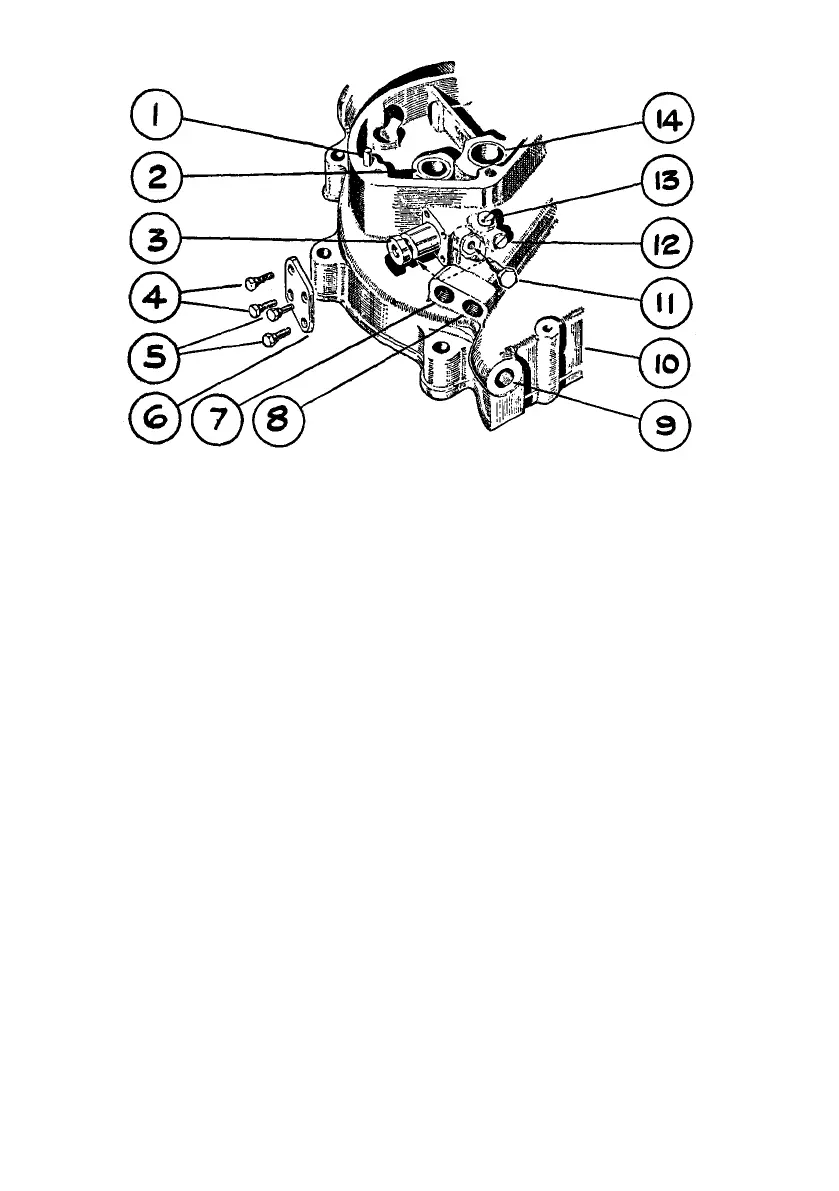
Illustration 14
The rotating oil pump plunger is here shown partially with-
drawn, together with the guide screw which registers in the
plunger profiled groove, thereby providing the recipro-
cating movement
(By courtesy of " Motor Cycling ")
1
2
3
4
5
6
7
8
DOWEL PEG, LOCATING TIMING GEAR
COVER.
BUSH, FOR INLET CAMSHAFT.
PLUNGER, FOR OIL PUMP.
BOLT, FIXING REAR END CAP.
BOLT, FIXING REAR END CAP.
REAR END CAP, FOR OIL PUMP.
TAPPED HOLE, FOR PIPE RETURNING
OIL TO OIL TANK.
TAPPED HOLE, FOR PIPE FEEDING OIL TO
OIL PUMP.
9
10
11
12
13
14
TAPPED HOLE, TO ACCOMMODATE
CRANKCASE DRAIN PLUG.
CRANKCASE, TIMING SIDE.
GUIDE SCREW AND PIN, FOR OIL PUMP
PLUNGER.
PLUG SCREW, FOR OIL PASSAGE.
PLUG SCREW, FOR OIL PASSAGE.
BUSH, FOR TIMING SIDE FLYWHEEL
AXLE.
TO REMOVE AND REPLACE THE OIL PUMP PLUNGER
Remove
Lower end of rocker box oil feed pipe by unscrewing union nut.
Both oil pump end caps.
Oil pump plunger guide screw with pin. (See illustration 14, No. 11.)
Oil pump plunger, by pushing at front and extracting from rear end of its housing.
Replace by :
Reversing above procedure.
36