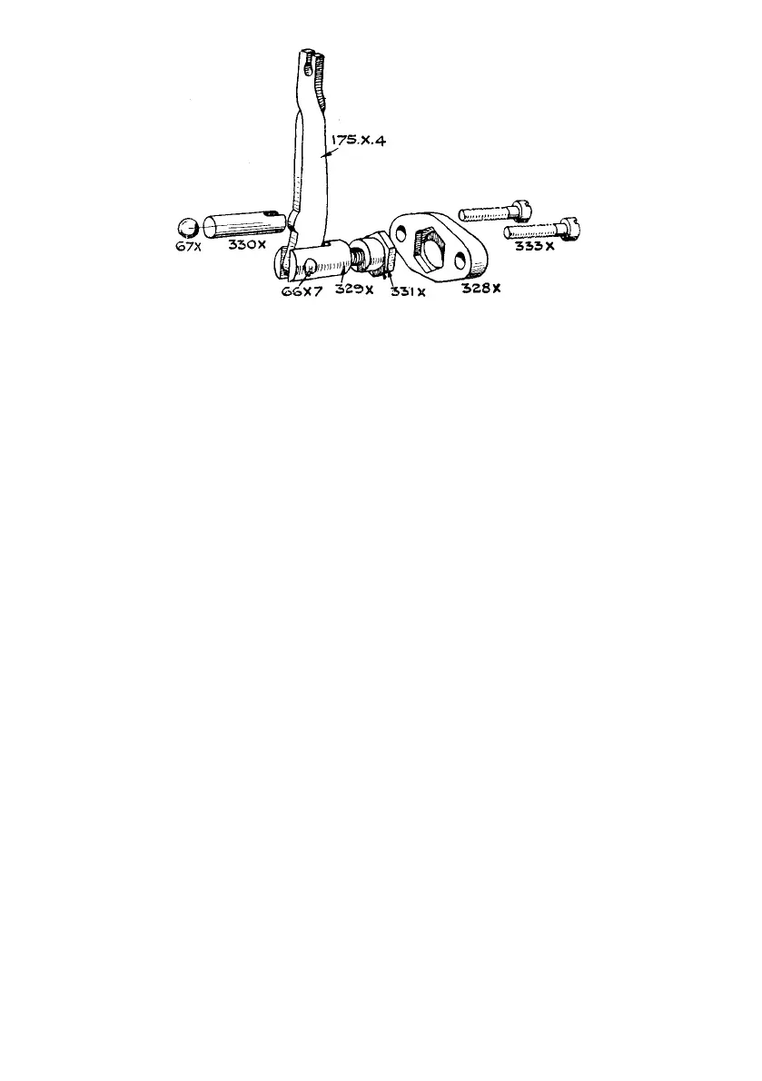
Illustration 18
Details of clutch operating lever
175-X-4
67-X
330-X
66-X-7
329-X
LEVER, OPERATING CLUTCH.
BALL (STEEL), FOR OPERATING
PLUNGER.
OPERATING PLUNGER.
PIN, OR AXLE, FOR OPERATING
LEVER.
FORK, FOR OPERATING LEVER.
331-X
328-X
333-X
SLEEVE, OR NUT, FOR OPERATING
LEVER FORK.
CAP, COVERING SLEEVE (SCREWED
TO KICK-STARTER CASE COVER).
SCREW, FIXING CAP TO KICK-
STARTER CASE COVER.
CLUTCH CABLE ADJUSTMENT
Minor adjustment of the clutch operating mechanism is obtained by :
Slacken lock nut on the cable adjuster screwed into the back of the kick-starter case.
To decrease the effective length of the clutch control cable, i.e., to take up play between
the control and the clutch thrust rod, unscrew the cable adjuster from the kick-starter
case. A few turns should be ample.
To provide a greater amount of play, screw into the kick-starter case the cable adjuster.
Finally, tighten lock nut on cable adjuster.
NOTE—The amount of play, or free movement, can easily be discovered by virtue of the
greatly increased resistance of the handlebar clutch control lever as the de-
clutching action commences.
To remove a clutch control cable
Remove the oil filler cap from the kick-starter case cover.
Screw right home the clutch cable adjuster that is located in the back of the kick-starter
case.
Disengage, from the operating lever, the clutch cable inner wire by operating through
the oil filler cap opening.
Completely unscrew the clutch cable adjuster.
Disengage, from the handlebar operating control lever, the clutch inner wire.
Pull cable, by its lower end, till removed from the machine, easing it through the frame
cable clips while doing so.
To replace a clutch control cable
Reverse the above instructions and, finally, adjust as detailed in the previous paragraph.
48