Ill
CD
PLAYER BLOCK
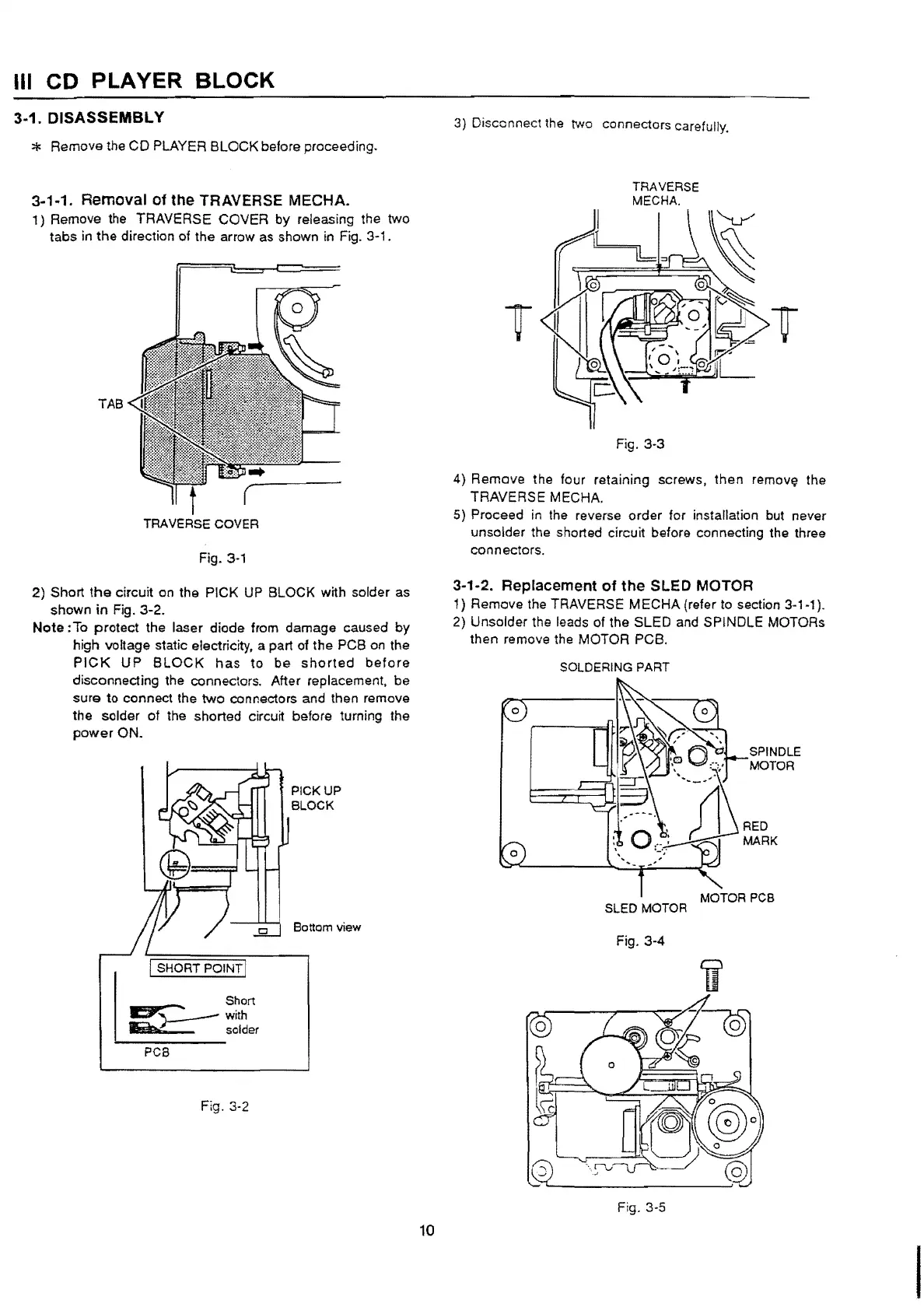
3-1. DISASSEMBLY
* Remove the
CD
PLAYER BLOCK before proceeding.
3-1-1. Removal
of
the TRAVERSE MECHA.
1)
Remove the TRAVERSE COVER by releasing the two
tabs
in
the
direction of the arrow
as
shown
in
Fig.
3·
1 .
TAB
TRAVERSE COVER
Fig.
3-1
2) Short
the
circuit on the PICK
UP
BLOCK with solder as
shown
in Fig. 3-2.
Note :To protect the laser diode from damage caused by
high voltage static electricity, a
part
of
the
PCB on the
PICK
UP
BLOCK
has
to
be
shorted
before
disconnecting the connectors. After replacement, be
sure to connect the
two
connectors and then remove
the solder of the shorted circuit before turning the
power
ON.
I SHORT
POINT!
Short
1:::::111'.;
" with
liiiii:w
solder
PCS
Fig. 3-2
PICKUP
BLOCK
Bottom view
10
3) Disconnect the two connectors carefully.
TRAVERSE
MECHA.
I
~.,
0
r
II
r
~:
Fig. 3-3
4)
Remove the four retaining screws,
then
remov~ the
TRAVERSE
MECHA.
5) Proceed
in
the reverse order for installation but never
unsolder the shorted circuit before connecting the three
connectors.
3-1-2. Replacement of the SLED MOTOR
1) Remove the TRAVERSE
ME
CHA (refer to section 3-1-1
).
2) Unsolder the leads of the SLED and SPINDLE MOTORs
then remove the MOTOR PCB.
0
0
SOLDERING PART
0
t?
-,,
•.~
0,-,,-
~~g~E
""
......
_
.....
~
,
rd
RED
\.
c)
MARK
MOTOR PCB
SLED MOTOR
Fig. 3-4
Fig. 3-5
 Loading...