.
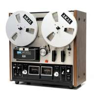
I. BUlLT-IN REEL RETAINER
To lock reel firmly into place, pull tip of retainer outward and
turn to left or fight.
2. SUPPLY REEL TABLE
3. REEL SIZE SELECTOR
Set to "10 in"
position when using 10-1/2" reels and to
"7 in"
position when using
7" or 5"
reels. When using 10-1/2" reels,
employ standard accessory reel adapter hubs.
4. CUE SWITCH
For precision cueing and editing. Refer to "Cue Switch",
page 6.
5. HEAD COVER
Houses (from left) Reverse Playback, Reverse Recording/Erase
combination, Forward Recording/Erase combination, and
Forward Playback GX Heads.
6. TAPE SPEED SELECTOR SWITCH
Set according to desired speed. For professional high fidelity
recording, 15 ips tape speed is recommended.
7. PINCH WHEEL
Presses against left capstan to transport tape.
.
This dual capstan system provides perfect tape stability in
both directions.
8. CAPSTAN
9. SENSING POLE/TAPE GOlDE
Sensing pole reverses tape direction (foward to reverse).
10. SHUT-OFF/TENSION LEVER
At the end of the tape when this lever drops, if tl1e Automatie
Shut-Off Switch is set to ON position, the automatic shut-off
circuit is activated to cut off the power of the entire unit.
Tension lever function provides proper tape tension.
11. DlRECTlON INDICATOR LAMPS
Lights to indieate direction of capstan motor rotation.
12. REVERSE SELECTOR SWITCH
Refer to "Automatie and Manual Reverse Recording and
Playback".
13. POWER SWITCH
14. SHUT-OFF SWITCH
Set to ON position for automatie shut-off. See item 9 above.
15. VU METER
Indieates left channel recording and playback levels. Normal
recording is
"0"
VU.
16. MIC-l/DIN INPUT LEVEL CONTROL
Controls Mic-l (left) and left channel Din input volume.
17. TAPESELECTORSWITCH
Set to S.R.T position when using Akai S.R.T (super range) tape
or other make low noise tape. Set to NORMAL when using
regular tape.
18. MIC-l/DIN INPUT LEVEL CONTROL
Controls Mic-l (right) and fight channel Din input volume.
19. VU METER
Indicates fight channel recording and playback levels. Normal
recprding level is
"0"
VU.
20. HEADPHONE VOLUME CONTROL
Controls headphone output volume. Set Line Out Volume
Control to
"0"
VU (position 5) and then adjust Headphone
Volume Control.
21. HEADPHONEJACK
Accomodates any low impedimce 8 n type stereo headphones
for monitoring or headphone listening.
22. BUlLT-IN REEL RETAINER
To lock reel firmly into place, puB tip of retainer outward and
turn to left or fight.
23. T AKE-UP REEL T ABLE
24. PAUSE SWITCH AND PAUSE INDICATOR LAMP
Convenient for temporarily suspending tape travel during
recording or playback. Pause Indieator Lamp lights to confirm
pause mode.
25. RECORDING SAFETY BUTTON
While holding this button at depressed position, depress
Forward Button to effect recording mode.
.,
~
26. MIC-2/UNE INPUT LEVEL CONTROt
Controls Mic-2 (Ieft) and left liDe input volume.
27. REWIND BUTION
Rewinds tape at high speed.
28. PINCH WHEEL
29. CAPSTAN
Presses against fight capstan to transport tape.
30. TAPE GUIDE
31. AUTOMA TlC STOP/TENSTION LEVER AND SENSING
POLE
At the end of the tape, when this lever drops, if the Automatic
Shut-Off Switch is at OFF position, the automatic stop circuit
is activated to stop reet movement. Also functions as sensing
pole for reserve to forward operation.
32. INDEX COUNTER & RESET BUTION
33. REVERSE BUTTON
Depress to effect manual reverse (changes direction of tape
from forward to reverse).
34. FAST FORWARD BUTTON
Advances tape of high speed.
35. FORWARD BUTTON
Advances tape for playback or recording mode.
36. STOP BUTION
37. MONITOR SWITCH
Depress SOURCE Monitor Switch to monitor source during
recording, and TAPE Monitor Switch for playback or private
headphone listening or for monitoring recorded signals during
recording mode.
38. UNE OUTPUT LEVEL CONTROL
Adjust left liDe output volume du ring playback.
39. TRACK SELECTOR SWITCHES
Left: tracks 1-4, Right: tracks 3-2, Left and Right: Stereo
40. MIC-2/UNE INPUT LEVEL CONTROL
Controls Mic-2 (right) and fight line input volume.
41. MIC-l MICROPHONE JACKS
42. UNE OUTPUT LEVEL CONTROL
Adjusts fight liDe output volume at playback time.
43. MIC-2 MICROPHONE JACKS
44. CYCLE CONVERSION SWITCH
Set to SO Hz or 60 Hz according to area power source.
45. A.c. OUTLETS
These extra AC outlets are unswitched (not inter-locked with
the Power Switch) so thaI power is applied even with the
GX-400D turned off.
46. UNE OUTPUT JACKS
Connects to tape input or aux jacks of external amplifier for
pla yback.
47. S.O.S/ECHO SELECTOR SWITCH
S.O.S: For Sound-on-Sound recording. Refer to page 11.
Echo: For recording with echo effect.
Normal; Normal recording.
.
Except when rnaking an S.O.S or an echo-effect recording,
this switch must always be set to NORMAL position.
48. DlN JACK
Enables inter-connectionwith an external amplifier with a single
Din cord.
49. RE MO TE CONTROL SOCKET
Accomodates Akai Remote Control Unit RC-I 7.
SO. UNIVERSAL VOLTAGE SELECTOR AND FUSE POST
Offers six stages of voltage for worldwide operation. Refer to
"Voltage and Cycle Conversion", page 13.
5 I. UNE INPUT JACKS
Connects to output jacks of external source.
52. DlN JACK INPUT SELECTOR SWITCH
When using the Din lack, if the output level of your external
amplifier is high, set this switch to HIGH, and of low, set to
LOW position.
rn
 Loading...