EasyManua.ls Logo

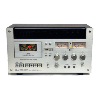
Akai GXC-570D

Akai GXC-570D
70 pages
To Next Page IconTo Next Page
To Previous Page IconTo Previous Page
Loading...
}.
NOISE
FILTER
}*
[RC
BOARD
CB-2027
sve
1®
(FD)
4
Ridscene
2)
fees
ae
fez]
-
)
oe
ears
OF
STOP
DETECTION
R.C
'
ena
§
woe]
te
BOARD
CB-2026
|
j
;
i
a
3
?
fad
ED
oa
i
ap
ie
:
£
ar
a
Me
3
)
leyee
Th
‘
5
Fa
3
‘oa
FS
EPEAT
SWITCH
PC
H
z
0
Bho
fit
ee]
foie
TE
Lo
wasn}
cas
nf
A
|
foe’
1BOARD
CI-5036
4
o—
FS
Ses
.
=
a
“|
s
i,
Han
one)
«
1
ot
on
at
5p
FE
ri
2
i
4
2 .
vas
z
©
|
5
:
i
2
i
Tie
3
Hae
|
*
ele
'
3
—
as
sty
wrt
cu
ca]
Be
ea
ay
ica)
em
7m
5
7q
Fe
Oe
CS
a
a
:
Peer!
Elen
aw
t
Pe
one
Beet
Et
a
OS)
5
7
|?
bier
aby
7
|
=
wa
ic)
3
Z|
a
A:
He.
@
:
“2
=
el
=
enh
ma
wah
FT
a3
ease
me
=
wae
anf
aT
—
;
wae
=
iat
-
dz
=
=
H
aye
#
i
#
#
Ei
i
194
-—@
=
=
*
lat
os
;
A
af
igigs
BouL
5
rT
ia}
ii
on
Fy
A.
SYSTEM
CONTROL
PC
Soa
7
=
.
1
To
Tove
swrten
cimcuiT
ta-------
+--+
+--+
TOUCH
SIMTK
CHU
1-1.
TAPE
SLACK
ELIMINATION
CIRCUIT
1)
Because
this
deck
employs
a
double
capstan
drive
system,
if
tape
with
a
great
deal
of
slack
is
used,
trouble
with
the
tape
tangling
around
the
capstan
is
likely
to
occur.
Even
if
only
slight
tape
slack
exists,
it
takes
time
after
effecting
a
forward
mode
to
obtain
proper
tape
tension,
which
results
in
a
continuous
poor
head-to-tape
contact
condition.
The
purpose
of
this
circuit
is
to
prevent
such
trouble
by
taking
up
tape
slack
prior
to
operation
for
proper
tape
tension
at-all
times.
2)
When
a
cassette
is
not
loaded,
TRIS
assumes
an
ON
condition
and
TR16
an
OFF
condition.
When
a
cassette
is
loaded,
cassette
detection
micro
switch
SW6
contacts
NC
side
(contact
point),
and
a
charge
current
flows
to
C7.
Within
this
charge
current
period,
TR15
is
turned
OFF
and
collector
voltage
increases.
Charge
current
flows
to
R52
and
C8
and
at
the
end
of
the
charge
current
period,
TR16
is
turned
ON
and
collector
current
flows.
This
current
passes
D81,
causing
the
take-up
motor
to
rotate,
and
at
the
same
time
passes
D82,
causing
the
supply
motor
to
rotate.
Thus,
the
tape
is
pulled
from
both
directions,
and
any
existing
slack
is
eliminated.
This
process
continues
until
the
C7
charge
current
ends,
at
which
time
the
circuit
returns
to
it’s
previous
state,
stopping
both
reel
motors.
H
SCHEMATIC-5
RWD
MODE
1-2.
PINCH
ROLLER
OPERATION
AND
REEL
MOTOR
ROTATION
TIMING
CIRCUIT
1)
If
reel
motor
starts
to
rotate
before
the
pinch
roller
reaches
the
capstan,
momentary
brake
tension
will
be
applied,
causing
the
tape
to
break
or
stretch.
This
circuit
is
for
the
purpose
of
elim-
inating
such
trouble
by
activating
reel
motor
revolutions
after
the
pinch
roller
has
contacted
the
capstan
when
playback
mode
is
effected.
2)
When
the
deck
is
set
to
Play
mode,
TR23
collector
voltage
is
increased,
TR24
is
turned
ON,
the
relay
functions,
and
the
pinch
roller
plunger
operates.
At
the
same
time,
as
a
result
of
an
increase
in
TR23
collector
voltage,
charge
current
passes
R11
and
D84
and
flows
to
C4.
During
the
period
of
this
flow
of
charge
current,
TRS
base
voltage
is
lowered,
and
because
TR5
is
turned
OFF,
the
take-up
motor
does
not
rotate.
However,
at
the
end
of
this
flow
of
charge
current,
TRS
base
voltage
increases,
TRS
is
turned
ON,
and
motor
Starts
to
rotate.
The
period
of
time
until
TRS
is
turned
ON
is
about
0.1
to
0.2
seconds.

Table of Contents

Related product manuals