EasyManua.ls Logo

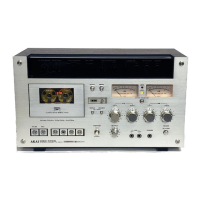
Akai GXC-570D

Akai GXC-570D
70 pages
To Next Page IconTo Next Page
To Previous Page IconTo Previous Page
Loading...
|
Par
eraeeen
ana
Step
Adjustment
Item
Result.
Remarks
Playback
Level
Adjustment
Recording
Level
Adjustment
(low
noise
tape)
Recording
Level
Chrome
Blank
Tape
0+0.5
dBm
(0.775V)
Set
Monitor
Switch
to
“TAPE”
Test
Tape
Adjustment
Supply
Signal
Mode
Point
333
Hz0
VU
VRI
S00B
Test
Tape
PLAY
(CA-5205)
Low
Noise
VRI
10kB
Blank
Tape
(left
channel)
1,000Hz0
vu
|
REC
|
VRib
10kB
recordin
(right
channel)
:
(CI-5028)
0+0.5
dBm
(0.775V)
Set
Monitor
Switch
to
“TAPE”
Refer
to
Note
-1)
Set
Monitor
Switch
to
3
Adjustment
1,000
Hz
0
VU
REC
“TAPE”
(chrome
tape)
recording
Refer
to
Note
-2)
Frequenc
ae
VRE
20
EB
cate
ie
P
(left
channel)
1,000
Hz
4
ReSponse
1,000
Hz
REC
|
VR2
SOkB
10°000
Hz
Set
Tape
selector
to
Adjustment
10,000
Hz
?
:
“LOW
NOISE”
:
(right
channel)|
Flat
response
(low
noise
tape)
—20
VU
:
:
(CI-5030)
recording
Frequency
Chrome
Blank
Tape
5
Response
ers
REC
VR3
100B
ae
Set
Tape
selector
to
Adjustment
:
(CI-5030)
:
“CHROME”
—20
VU
Flat
response
(chrome
tape)
;
recording
Low
Noise
Recording
Level
Blank
Tape
VR1,
VR1b
6
Confirmation
1,000
Hz
REC
10
kB
0+0.5
dBm
|
Refer
to
Note
-3)
(low
noise
tape)
0
VU
(CI-5028)
recording
VU
Meter
VR2,
VR2b
Set
Meter
selector
to
7
Sensitivity
1,000
Hz
STOP
5
kB
0VU
“VU
METER”
Adjustment
(CI-5028)
Refer
to
Note
4)
Peak
Meter
VR3,
VR3b
Set
Meter
selector
to
8
Indication
1,000
Hz
STOP
10
kB
-8
VU
“PEAK
METER”
Adjustment
(CI-5028)
Refer
to
Note
4)
Chart
1
NOTES:
1.
Recording
level
adjustment
volumes
(REC
CAL)
VR5
and
VR6
are
not
located
on
the
Pre-Amp
P.C
Board’
22
as
in
the
case
of
an
ordinary
tape
deck,
but
are
installed
on
the
front
panel.
When
adjusting
VR1
and
VRIb,
set
VR5
and
VR6
to
center
position.
carried
out
with
as
little
error
as
possible.
.
Use
the
following
cassette
measuring
tape:
Low
Noise
Tape:
Chrome
Tape:
Fuji
C-60LN
.
After
low
noise
tape
adjustments,
confirm
recording
level
only.
.
Following
Step
4
frequency
response
adjustment,
because
the
recording
level
may
be
slightly
changed,
confirnr
level
and
if
necessary,
carry
out
Step
2
Adjustment
again.
.
Set
Monitor
Switch
to
“SOURCE”
and
supply
a
1,000
Hz
signal
to
line
input
to
obtain
a
0
dBm
line
output
level.
.
Because
each
of
these
adjustments
are
vital
to
perfect
Dolby
N.R.
circuit
operation,
be
sure
that
they
are
BASF
#SM
Chrome
C-60

Table of Contents

Related product manuals