D145H4502 Ed. 01
20
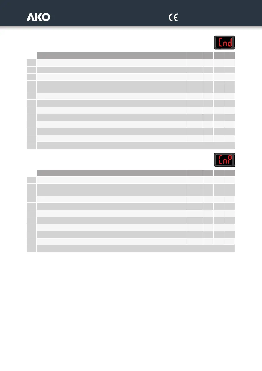
Level 1.- CONDENSATION CONFIGURATION
Description Units Min. Def. Max.
F01 Condensation pressure / temperature set point bar F03 14 F02
F02 Condensation set point upper limit (It cannot be set above this limit) bar F03 65 65
F03 Condensation set point lower limit (It cannot be set below this limit) bar -0.7 -0.7 F02
F04
Fan rotation type: 0=Balancing, depending on the operation time
1=Sequential (the last in is the first out)
0 1 1
F05 Fan control type: 0=Neutral zone; 1=Proportional 0 0 1
F06
Condensation regulation bandwidth bar 0.0 2.0 50
F07 For fans when the compressors stop 0=No; 1=Yes 0 0 1
F08 Floating condensation 0=No; 1=Yes 0 0 1
F09 Integral time (PID inverter control) sec. 2 5 10
F10 Floating condensation minimum set point value (see remark 1) ºC -50 28 99.9
F11 Condenser temperature delta ºC 6 12 20
EP Output to level 1
Level 1.- PROBE CONFIGURATION
Description Units Min. Def. Max.
P01
Probe type selection 0=4-20 mA; 1=0.5 - 4.5 V; 2=NTC 0 1 2
P02
Probe to be displayed: 0=Probe 1 (Aspiration) 1=Probe 2 (Discharge);
2=Probes 1 and 2 in carousel
0 0 2
P03 Value 4 mA / 0.5 V (According to P01) probe 1 bar -60 -1 65
P04 Value 20 mA / 4.5 V (According to P01) probe 1 bar -60 9 65
P05 Probe 1 calibration (Offset) bar -20 0 20
P06 Value 4 mA / 0.5 V (According to P01) probe 2 bar -60 0 65
P07
Value 20 mA / 4.5 V (According to P01) probe 2 bar -60 34 65
P08 Probe 2 calibration (Offset) bar -20 0 20
P09 Calibration of the outside temperature probe for floating condensation ºC -20 0 20
EP Output to level 1
Remark 1: The equivalent value in pressure is calculated depending on the refrigerant gas specified in the wizard.