D145H4502 Ed. 01
5
Initial setup
The unit has a wizard that configures the unit’s parameters and assigns the input and output functions
according to the installation type chosen.
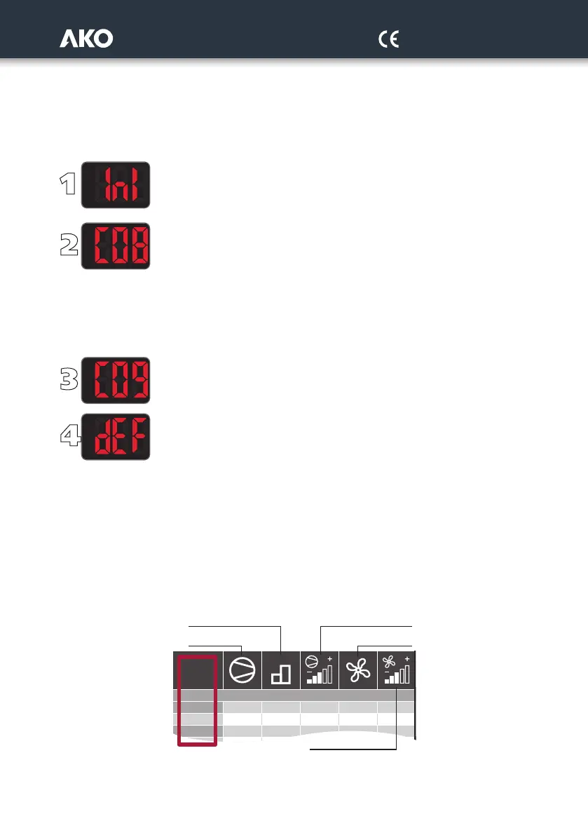
When connecting the power supply for the first time, the Configuration Wizard will start, displaying the message INI
on screen. Follow the 4 steps detailed below and the unit will be ready to operate:
By using keys N and Q, select the most suitable option according to the installation type in
accordance with the “WIZARD” table on page 7 and press SET. The wizard configures
the equipment parameters and assigns the input and output functions according
to the installation type chosen.
Select the refrigerant gas type used from amongst the following options:
0=R404A 1=R134A 2=R407A 3=R407F 4=R410A 5=R450A
6=R513 7=R744 8=R449A 9=R290 10=R32 11=R448A
12=R1234ze 13=R23 14=R717 15=R407C 16=R1234yf 17=R22
18=R454C 19=R455A 20=R507A 21=R515B 22=R452A 23=R452b
24=R454A 25=R12 26=R114 27=R142B 28=R170 29=401A
30=R402A 31=R407B 32=R413A 33=R417A 34=R422A 35=R422D
36=R427A 37=R438A 38=R500 39=R502 40=R503 41=R600
42=R600A
Select the primary and secondary display units from amongst the following options:
0=bar-ºC; 1=psi-ºF; 2=psi-ºC; 3=bar-ºF; 4=ºC-bar; 5=ºF-psi; 6=ºC-psi; 7=ºF-bar
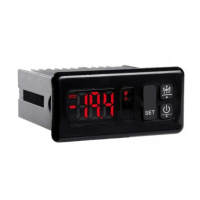
Configure the rest of the parameters to their default value? :
0=No, the configuration is kept for all the parameters except for C01, C02, C04, C05 C06,
C08 and C09.
1=Yes, all the parameters are configured to their default value (see parameters table)
(This option does not affect parameters C01, C02, C04, C05 C06, C08 and C09)
In order to start the wizard again, disconnect the unit’s power supply, reconnect it and, during the subsequent 8 se-
conds, press the key sequence N, Q, SET.
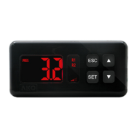
“WIZARD” table description
The “WIZARD” annex table is divided into 3 groups of columns.
The first group describes the different types of installation (no. of compressors and fans, whether they have a conver-
ter, etc.) associated to their INI option.
Installation
2
3
1
4
INI
111--
2 1 2 - -
1
Stages by compressor Compressors with inverter
Compressors
without inverter
Fans without
inverter
Fans with inverter