D145H4502 Ed. 01
6
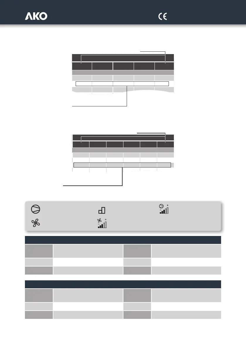
The second group specifies the function assigned to each relay depending on the INI option selected.
Relays
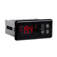
The third group specifies the function assigned to each digital input depending on the INI option selected.
Inputs
Legend
FUNCTION OF THE OUTPUTS
CV: RUN inverter output (compressor)
Cxa, Cxb, Cxc:
Output stages 1, 2 and 3 of
compressor x
FV: RUN inverter output (fans) Vx: Output fan without inverter
Cx: Output compressors without inverter AL: Alarm output
FUNCTION OF THE INPUTS
T-VAR-C1: Thermal input frequency inverter
(compressor)
T-Vx:
Thermal input fan
T-VAR-F: Thermal input frequency inverter (fans) H.P.: Input high pressure switch
T-Cx: Thermal input compressor L.P.: Input low pressure switch
x: Compressor or fan no.
a, b, c: Compressor stages
I1 I2 I3 I4 I5
T-VAR-C1 T-C2 T-VAR-F - L.P. H.P.
T-VAR-C1 T-C2 T-VAR-F - L.P. H.P.
T-VAR-C1 T-C2 T-C3 T-VAR-F L.P. H.P.
T-C2 T-VAR-F
R2 R3 R4
C2 C2a FV
C2 C2a C2b
C2
1
Compressors without inverter Compressor with inverter
Number of stages per
compressor
Fans without inverter Fans with inverter
Relays R1 to R5
Inputs I1 to I6
Function assigned to each relay
depending on the INI option selected*
Function assigned to each input
depending on the INI option selected*