D145H4502 Ed. 01
22
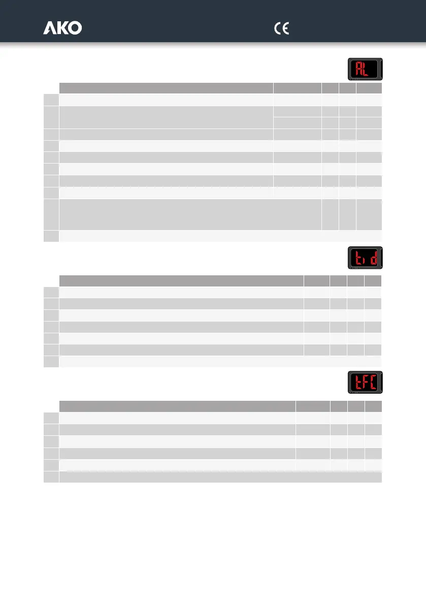
Level 1.- CONFIGURATION OF PROTECTIONS AND ALARMS
Description Units Min. Def. Max.
A01 Number of active compressor stages with error in probe 1 0 0 ***
A02 Number of active fans or inverter % with error in probe 2
Without inverter 0 C05 C05
With inverter 0
100%
A03 Low pressure alarm in probe 1 bar -0.7 0 65
A04 Low pressure alarm differential bar 0.1 1.0 20
A05 High pressure alarm in probe 2 bar -0.7 20 65
A06
High pressure alarm differential
bar 0.1 1.0 20
A07
Alarm delay after reaching the value
0 60 999
A08
Delay of temperature alarms in the start-up.
seg. 0 0 255
A9
High pressure alarm limit (per digital input) per hour without manual reset.
(If I07 or I08=1) (0=deactivated) Once the limit has been exceeded a manual reset will
be required for each new alarm.
0 0 255
EP Output to level 1
Level 1.- ACCES AND INFORMATION CONTROL
Level 2
Description Units Min. Def. Max.
b20 Address for units with communication 1 1 255
b21 Communication speed: 0:9600 bps; 1:19200 bps; 2:38400 bps; 3:57600 bps 0 0 3
L5 Access code (Password) 0 0 999
PU Programme version - - -
Pr Programme revision 1 - -
Psr Programme sub-revision (Information) - - -
EP Output to level 1
Level 1.- OPERATION TIMES
Description Units Min. Def. Max.
c1
This shows the operation time for the compressor or fan 1
Hours x10 - - -
c2
This shows the operation time for the compressor or fan 2
Hours x10 - - -
c3
This shows the operation time for the compressor or fan 3
Hours x10 - - -
c4
This shows the operation time for the compressor or fan 4
Hours x10 - - -
c5
This shows the operation time for the compressor or fan 5
Hours x10 - - -
EP Output to level 1
*** The number of stages depends on the configuration selected in the wizard.
 Loading...