GB
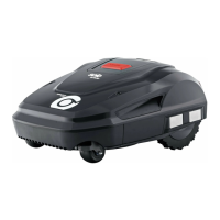
48 Robolinho 700/1200/2000
Installation
■
Steep ascents and descents of more
than 45% (24°)
■
Bodies of water (e.g. ponds, streams,
swimming pools, etc.) and their demarca-
tion to the grass surface
■
Shrubs and hedges that can become
broader
4.4 Setting up the base station(03/a)
1. Place the base station (01/1) at right angles
to the planned location of the boundary cable
as described below:
■
Level (check with spirit level)
■
Straight and level entrance and exit
■
Not arched (the charging station must not
bend or tilt during subsequent tightening
of the screw nails)
2. Fix the base station (03/2) to the floor with
four screw nails (03/1).
4.5 Installing the boundary cable
4.5.1 Connecting the boundary cable to the
base station (03/b)
1. Pull the boundary cable(03/4) out of the
packaging.
2. Remove the cover of the cable shaft (03/3)
on the connection(03/A).
3. Insulate the end of the boundary cable(03/6)
and insert into the terminal(03/7).
4. Close the terminal.
5. Lead the boundary cable through the strain
relief(03/5) out of the cable shaft with cable
reserve.
NOTE
The cable reserve allows smaller correc-
tions to be carried out on the cable guide
later.
6. Place the cover on the cable shaft.
4.5.2 Routing the boundary cable (01)
The boundary cable can be laid on the lawn and
as much as 10 cm under the turf. Laying under
the turf can be carried out by the dealer.
Both variants can be combined with one another.
IMPORTANT!
Danger of damaging the boundary ca-
ble
If the boundary cable is damaged or cut,
the transmission of the control signals to
the appliance is no longer possible. In
this case, the boundary cable must be
repaired or replaced. The boundary ca-
bles are available from AL-KO.
■
Always route the boundary cable di-
rectly on the ground. If necessary,
secure with an additional lawn peg.
■
When laying the boundary cable and
during operation, protect the bound-
ary cable from damage.
■
Do not dig or scarify in the vicinity of
the boundary cable.
1. Attach the boundary cable at regular intervals
with lawn pegs or route it underground (at a
max. depth of 10cm).
2. Route the boundary cable around obstacles:
see chapter 4.5.3 "Excluding obstacles",
page48.
3. Create corridors between individual mowing
areas: see chapter 4.5.4 "Enclosing corridors
(01/h)", page49.
4. Exclude excessive upward or downward
slopes: see chapter 4.5.5 "Excluding down-
ward slopes", page49.
5. Create loops of cable: see chapter 4.5.6
"Creating loops of cable (07)", page49.
6. After completing the routing of the boundary
cable, connect to the connector (03/B) of the
base station: see chapter 4.5.1 "Connecting
the boundary cable to the base station (03/
b)", page48.
4.5.3 Excluding obstacles
Depending on the surroundings of the working ar-
ea, the boundary cable must be routed at differ-
ent distances to obstacles. Use the ruler that can
be removed from the packaging to determine the
correct distance.
 Loading...