11
4:4 REPLACING THE SPARK ELECTRODE
When replacing the spark electrode, also replace the
ame sensor.
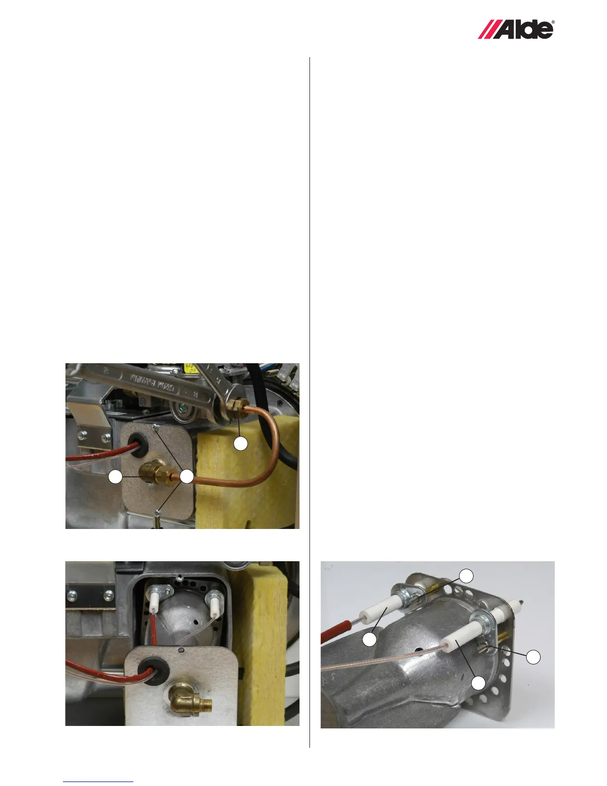
1. Detach the burner as per instructions in 4:3.
2. Remove the nut (g. 13 A) and pull the spark electrode
(g. 16 B) straight backwards.
3. Fit the new spark electrode and secure it. Check that the
distance between the tip of the spark electrode and the
mesh cover of the burner is 2.5-3.5 mm, and that the
spark electrode is correctly positioned (see g. 6).
4. Fit the burner in accordance with instructions and test-
start the boiler.
Fig 11.
Fig 12. Fig 13.
A
B
C
D
A
B
C
4:5 REPLACING THE FLAME SENSOR
When replacing the ame sensor, also replace the
spark electrode.
1. Detach the burner in accordance with 4:3.
2. Remove the nut (g. 13 C) and pull the ame sensor
(g. 13 D) straight backwards.
3. Fit the new ame sensor, ensuring that the tip of the
ame sensor is positioned above the burner in accor-
dance with g. 6. Secure the ame sensor.
4. Fit the burner in accordance with instructions and test-
start the boiler.
4:3 REPLACING THE BURNER
Applies to boiler models 3000 927 and later. If the
burner is replaced, burner 3000 516 should be installed.
1. Remove the cover and end plate from the boiler.
2. Detach the spark electrode and sensor cables from the
electronic ignition unit.
3. Using two spanners, unscrew the nut on the gas pipe
(g. 11 A) between the burner and the solenoid valve
(g. 11 B).
4. Remove the end plate with burner by slackening the
screws (g. 11 C) on the burner housing.
5. Pull the end plate with burner straight out of the burner
housing (g. 12).
6. Fit the new burner (insert it straight in) and secure it via
the end plate in the burner housing (g. 11 C).
7. Secure the gas pipe to the solenoid valve (g. 11 B) and
to the burner (g. 11 A). Remember to check that the
cones are correctly tted to the pipes. Using two span-
ners, tighten the nuts on the gas pipe to 7-9 Nm (g 11).
8. Fit the ignition spark and ame sensor cables to the
electronic ignition unit.
NB! Items 9-12 shall be ignored on boilers with manu-
facturing no 3000 9xx B and on boilers where burner
3000 516 is installed.
9. Adjust the pressure switch screw 1/2 turn clockwise
10.Remove the as in item 4.2 and the under the inlet plate
under impeller by removing the two screws.
11.Install the new inlet plate, and then put back the old one,
two screws.
12.Remount the fan in reverse order.
NB! Take care that the impeller does not get damaged
during tting. Check that the fan does not make an
unpleasant noise.
13.With the boiler operating, check the system and con-
nections for any leaks using a leak detector spray. Once
this is done, t the end plate and cover.