14
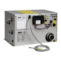
Fig 21.
4:7:2 REPLACING THE 2 KW HEATING
CARTRIDGE
1. Switch off 230 V power supply
2. Drain the glycol mixture from the heating system.
3. Remove the cover and end plate.
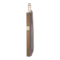
4. Remove the burner together with the solenoid valve (g.
21). Do not slacken the gas pipe, this is in order to avoid
having to check sealing.
5. Remove the cables from the heating cartridge.
6. Slacken the two plate screws and remove the sup-
porting angle bracket from the heating cartridge (does
not apply to boilers with serial numbers of 4445 or
higher).
7. Slacken the nut in the centre of the electrical heating
cartridge electrode and unscrew it approximately 10 mm
(g. 22)
8. Tap the nut lightly to release the rubber plug and extract
the heating cartridge by pulling straight backward. If
there is a T screw on the heating cartridge (the screw
has a groove), the nut must be unscrewed sufciently
for the T screw to be turned a quarter turn before the
heating cartridge can be pulled out.
NB! Leave the nut on the screw, with several turns
of thread in it.
9. Clean round the edges where the old heating cartridge
was. Then t the new heating cartridge. Before tting
it, check the direction of the T screw, push the heating
cartridge in and turn the T screw a quarter turn. Then
pull the nut so that the T screw comes into the correct
position (the screw should be at the same height as the
cable connections). Tighten to 4 Nm. Check that the T
screw projects 15-18 mm from the nut (otherwise there
is a risk that the T screw is not in the right position).
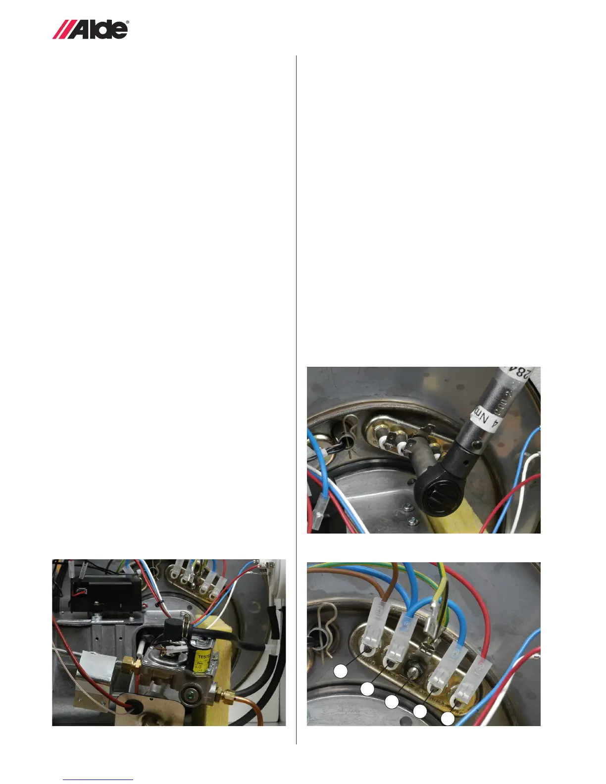
10. Any angle bracket should not be tted. Fit the solenoid
valve in accordance with the instructions. Connect the
cables as shown in g. 23 (A=brown, B=blue, C=yellow/
green, D=red). Fit the cover and end plate. Add glycol
mixture. Bleed and test-run the boiler.
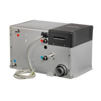
Fig 22.
A
B
C
B
D
Fig 23.
 Loading...