12
Fig 16.
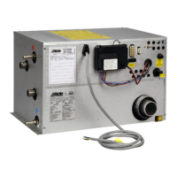
4:6 REPLACING THE SOLENOID VALVE
For boilers with serial no. from 04445 and upwards.
1. Remove the cover and end plate on the boiler.
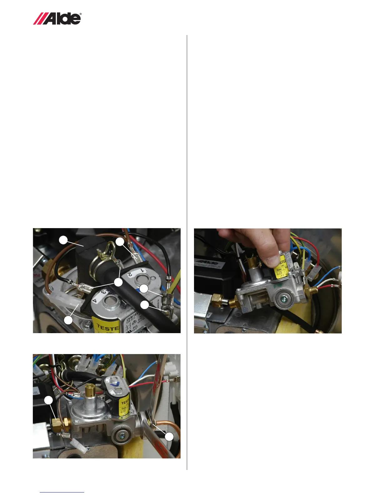
2. Unfasten the cables (black, brown and yellow/green) on
the solenoid valve (g. 14 A-C).
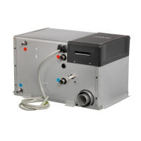
3. Using two spanners, slacken the nuts on the incoming
gas pipe (g. 15 A) and the gas pipe to the burner
(g. 15 B), and remove the rubber cap from the soft
start valve (g. 14 D).
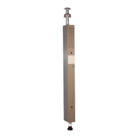
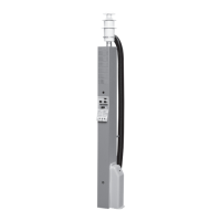
4. Extract the solenoid valve (g. 16) and t the new one
by following the instructions in reverse order.
5. Using two spanners, tighten the nut on the incoming gas
pipe to 25-30 Nm, and the gas pipe to the burner to 7-9
Nm. With the boiler operating, check the system and
connections for any leaks using a leak detector spray.
6. Fit the end plate and cover.
For boilers where the solenoid valve is tted to the
burner housing (up to serial no. 04444).
1. Remove the cover and end-plate on the boiler.
2. Unfasten the cables (black, brown and yellow/green) on
the solenoid valve (g. 14 A-C).
C
A
B
B
D
Fig 15.
Fig 14.
3. Using two spanners, slacken the nuts on the incoming
gas pipe (g. 15 A) and the gas pipe to the burner (g.
15 B), and remove the rubber cap from the soft start
valve (g. 14 D).
4. Detach the pressure switch hoses to and remove the
insulation next to the burner housing.
5. Unscrew the two plate screws which fasten the gas
valve angle bracket to the burner housing.
6. Extract the solenoid valve and transfer the angle bracket
to the new solenoid valve (attached underneath with a
screw).
7. Fit the new solenoid valve by following the instructions in
reverse order.
8. Using two spanners, tighten the nut on the incoming
gas pipe to 25-30 Nm, and the gas pipe to the burner to
7-9 Nm. Remember to check that the bevels are cor-
rectly tted to the pipes. With the boiler operating, check
the system and connections for any leaks using a leak
detector spray.
9. Fit the end plate and cover.
A
A
B
 Loading...