15
4:8 REPLACING THE OPERATING
THERMOSTAT
1. Remove the cover on the boiler.
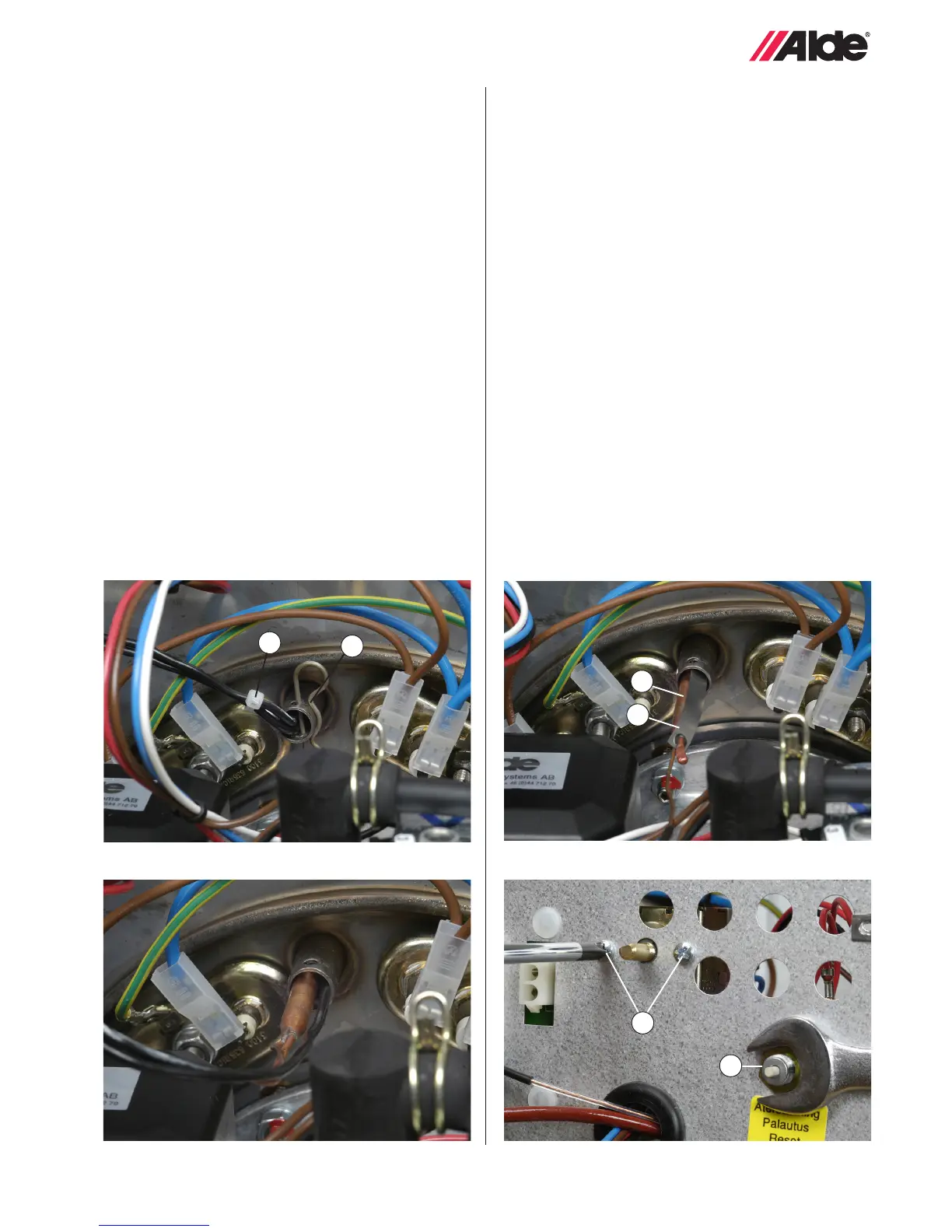
2. Remove the locking clip (g. 24 A). Remove the split pin
(g. 24 B) on the immersion pipe. Remove the overhea-
ting protection device sensor rst (g. 25), and then the
operating thermostat sensor (g. 26 A).
3. Unscrew the two screws which secure the operating
thermostat (g. 27 A) to the fastening plate, and remove
the cables from the at-pin connections.
4. Transfer the contact spring (g. 26 B) to the new opera-
ting thermostat. The spring must be tted with the rear
end of the bulb uppermost, so that it pushes the sensor
downwards into the immersion pipe.
5. First insert the operating thermostat sensor all the way
to the very end of the immersion pipe. Then insert the
overheating protection device sensor as far as possible.
Fit the split pin on the immersion pipe.
6. Attach the operating thermostat to the service panel
(NB! Use the original screws only) and connect the
cables in accordance with g. 2 (blue, grey and two
red).
7. Fit the cover and test-run the boiler.
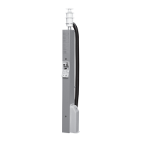
Fig 25.
Fig 27.
A
B
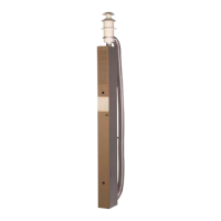
Fig 24. Fig 26.
4:9 REPLACING THE OVERHEATING
PROTECTION DEVICE
1. Remove the cover on the boiler.
2. Remove the locking clip (g. 24 A). Remove the split pin
(g. 24 B) on the immersion pipe and take out the
sensor (g. 25).
3. Remove the black plastic cap and unscrew the nut
(g. 27 B) which holds the overheating protection device
to the service panel. Release the cables (g. 2 A) from
the at-pin contacts and change the overheating prote
tion device.
4. Fit the new overheating protection device by following
the instructions in reverse order. Test-run the boiler.
A
B
A
B