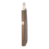
MOUNTING OF DECK/
ROOF FLUE
The boiler may only be mounted with
the original ue. The ue must not be
blocked.
The deck/roof ue should be mounted
on a level base, (however, a maximum
of 30º roof slope). Deck/roof ue shall
be located at least 500mm from open-
ings, windows, ventilation openings and
fuel relling pipes.
Object must not be mounted on the
deck/roof within a radius of 200mm from
the ue.
That part of the deck/roof ue that is
above deck shall be protected with pro-
tective netting or similar if there is a risk
of it being rubbed against.
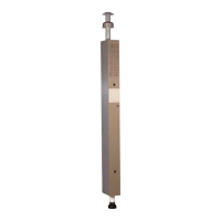
Mark the centre of the location where
the ue is to be mounted, or drill a Ø
76mm hole through the deck/roof.
Mount the ue from the outside of the
deck/roof. Seal between mounting
washer (C 4) and deck/roof (C 5) with
sealing compound for automobile body
application, and screw down the ue
with 6 plate screws (C 6).
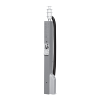
MOUNTING OF WALL FLUE
The boiler may only be mounted with the
original ue. The ue must not be
blocked.
The wall ue should be mounted on as
at a surface as possible, and also so
that air can freely circulate past the ue.
The ue should not be mounted closer
than 300mm sideways on from an open-
ing window or ventilation inlet.
A ue must not be mounted under a
window that can be opened, or a ven-
tilation inlet, see drawing. If the ue is
mounted closer than the measurements
given above, a window circuit-breaker
shall be installed that shuts off the LPG
gas supply when the window is open.
To secure the function of the boiler, no
objects shall be installed closer then
300mm from the ue (not a requirement
from the authorities).
NOTE that current national regula-
tions must be followed.
The distance from ue to relling posi-
tion or ventilation for fuel shall be at
least 500mm.
Mark the place where the ue is to be
located. Then drill a Ø 83mm hole. First
mount the gasket (B 7) and then screw
down the ue (B 8) with the 6 plate
screws (B 9). Note that the ue shall be
mounted with the bend upward (the ue
also has TOP OBEN marked on it). After
that, mount the plastic cap (B 10) with
the two screws provided (B 11).
WINDOW
Prohibited zon
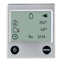
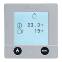
These instructions deal with the
installation and assembly of boiler,
control panel and expansion tank.
Read these instructions carefully
before assembling the boiler.
These instructions have been approved
for the Alde Compact 3010 boiler,
assembled in boats of up to 24m in
length in accordance with CE no 0845
BP-0003 and EMC e5 02 0136. Installa-
tion and repairs may only be carried out
by a professional. National regulations
must be followed when installing the
3010 Alde boiler. The requirements of
the ISO 10239, Recreational Craft Direc-
tive and Boat Safety Scheme must be
adhered to.
TECHNICAL DATA
Measurements/Weight:
Boiler height: 310 mm
Boiler depth: 340 mm
Boiler width: 510 mm
Weight: 14 kg (without uid)
Gas: Propane Butane
Output 1: 3,3 kW 3.8 kW
Consumption: 245 g/h 275 g/h
Output 2: 5,5 kW 6,4 kW
Consumption: 405 g/h 460 g/h
Pressure: I3+ 28-30/37 mbar
I3B/P 30 mbar
Volume/Pressure/Temp.
Liquid volume radiator water: 3.5 litres
Liquid volume warm water: 8.4 litres
Max pressure radiator water: 0.05 MPa
(0.5 bar)
Max pressure warm water: 0.3 MPa
(3.0 bar)
System temperature: max 85°C.
230 V ~
Output element: 1 x 1050 W
Output element
(2 or 3kW): 1 x 2100 W
12 V DC
Current consump.:1 amp (max)
Fuse: 3.15 amp+/3.15 amp-
INSTALLATION OF BOILER
The boiler can appropriately be located
in a wardrobe or storage space. The
boiler should be protected against
splashing of water, exhaust gases, etc.
In choosing the location, consideration
should also be given to dismantling the
service hatch (A 1) and that space will be
available for replacement of components
during service. The boiler should not be
put in engine compartments. The data
plate on the boiler shall be legible after
installation. The measurements given in
Fig. A for building in are recommended
minimum measurements with mounting
of the boiler.
The space where the boiler is to be
assembled must be ventilated, with a
ventilation area of at least 70cm2.
The boiler shall be screwed down onto
the oor through the holes in the xing
brackets (A 2).
Fig A
1. Service lid
2. Fastening points
MOUNTING OF INLET/
EXHAUST HOSE
Hose length with deck/roof ue: min.
2.0 and max. 3.5m.
Hose length with wall ue: min. 0.5
and max. 2m.
Measure and cut the required length
of inlet hose (Ø 75mm). The exhaust
hose (Ø 50mm) should be cut off so it
becomes approximately 50 mm longer
than the suction hose. Applies to hose
lengths over 1 m. Note that the hose
shall go in 20mm to the hose sleeves.
Push the exhaust hose into the inlet
hose. First mount the exhaust hose B,C
12) on the ue and tighten it with a hose
clip ( B,C 13).
Then put on the inlet hose (B,C 14) and
tighten with the other hose clip (B,C
15). After that, mount the hoses in the
same way on the boiler. Staple the hose
(B 16) on c/c 600mm or equivalent.
NB! Check the lay to ensure that water
can not be retained in the inlet/exhaust
hose.