MicroVerb/MicroVerb II Service Manual 1.00 3 3/7/2003
4.2
The Shaft Encoder
At first the shaft encoder
circuitry may appear more
complex than is necessary to just
switch programs. The reason for
the extra circuitry is to ensure that
noise isn't generated when
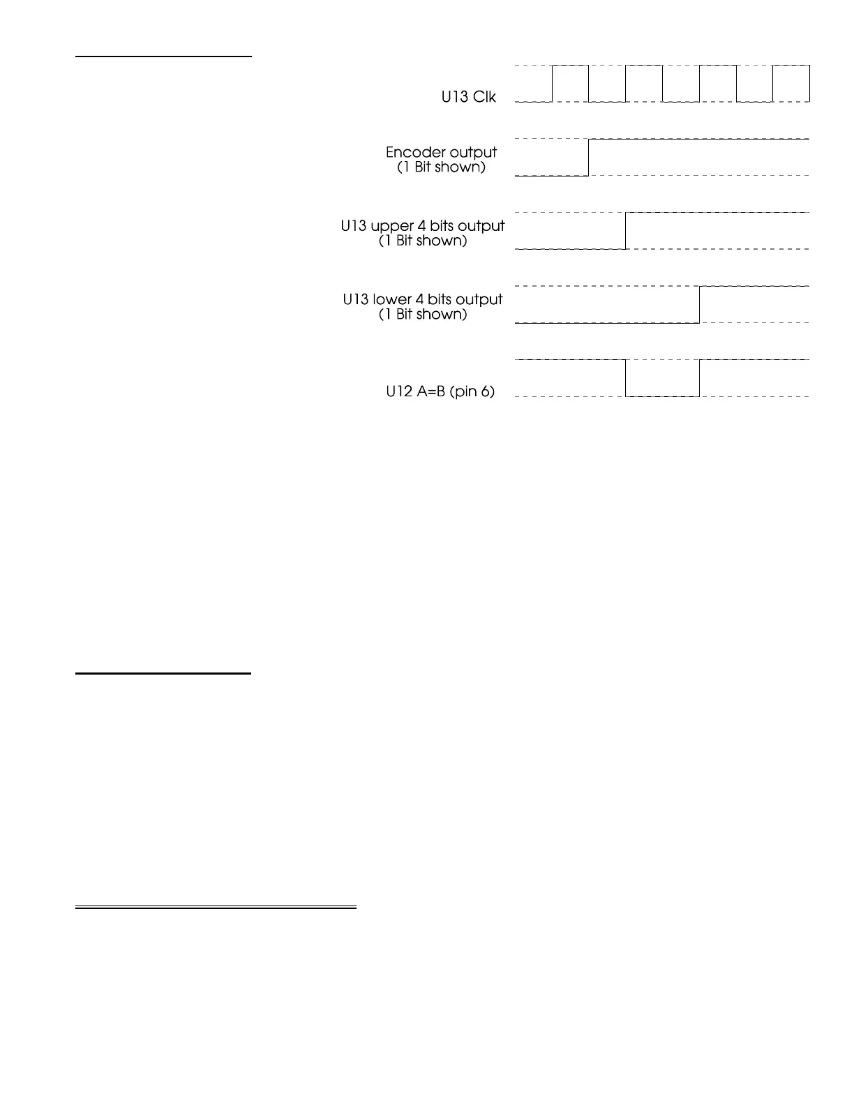
switching programs. Diagram 3
shows the important signals
present during preset switching
(only 1 bit is shown for the
encoder and latch, however, the
principal applies to all 4 bits).
Output from the shaft encoder is
latched by U13 (note that the 4
outputs of latch that correspond
to the outputs of the encoder are
fed back to the other 4 data
inputs of the latch). Any time that
the shaft encoder changes, the
upper 4 bits of the latch will be different from the lower 4 bits for exactly 1 clock cycle (on the next
clock pulse, the lower 4 bits will change to the new value). 4 bit magnitude comparator U12 is used
to detect these changes. Normally the
A=B
line of U12 (pin 6) stays high (the upper and lower 4 bits
from U13 are equal) until the shaft encoder changes position. At this point, U12
A=B
drops low,
discharging C23. One U13 clock cycle later
A=B
again raises high allowing C23 to charge slowly
through R39 (D7 provides protection for
A=B
during those times when
A=B
is high and C23 still has
very little charge on it yet). Now note the line that travels from the junction of C23 and R39, via U11,
to the
A12
line of the EPROM U1. This has the affect of temporarily forcing all use of the EPROM
address buss to be limited to the lower half of the address space. The algorithms in this half of
memory were written simply to clear the DRAMs of existing data during program changes, thus no
data - no noise!
4.3
Overflow Indicator
Due to the necessity of trying to convey several possible states with a single tricolor LED
requires a small amount of logic (U14). The 3 states that need to be covered are:
♦ No signal input-LED is orange
♦ Signal is present-LED is green
♦ The ASIC is experiencing a math overflow-LED is red
Whether or not a signal is present, it is input to the logic via Q1. Overflow conditions are sent
to the logic from the ASIC. When no signal is present, the
EPRMADR7
line of the ASIC is used to
switch between the red and green LED portions to simulate the appearance of orange.
5.0 Successive Approximation
Successive approximation is a "divide and conquer" approach to the process of analog to
digital conversion. The idea here, is to divide the task into short, manageable sections. Each
significant binary weight (starting with the Most Significant Bit) is taken in turn, thus requiring
only 12 comparisons to achieve a final value.
The process begins with the input "sample and hold circuit". 1 switch of U9 (4053) is
turned on, allowing the input sample capacitor (C20) to charge (or discharge) to the level of the
current input signal. When the switch is turned off, the capacitor will hold that level indefinitely
Diagram 3