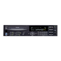
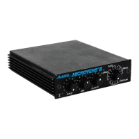
MicroVerb/MicroVerb II Service Manual 1.00 2 3/7/2003
4.0 Digital Signal Paths
4.1
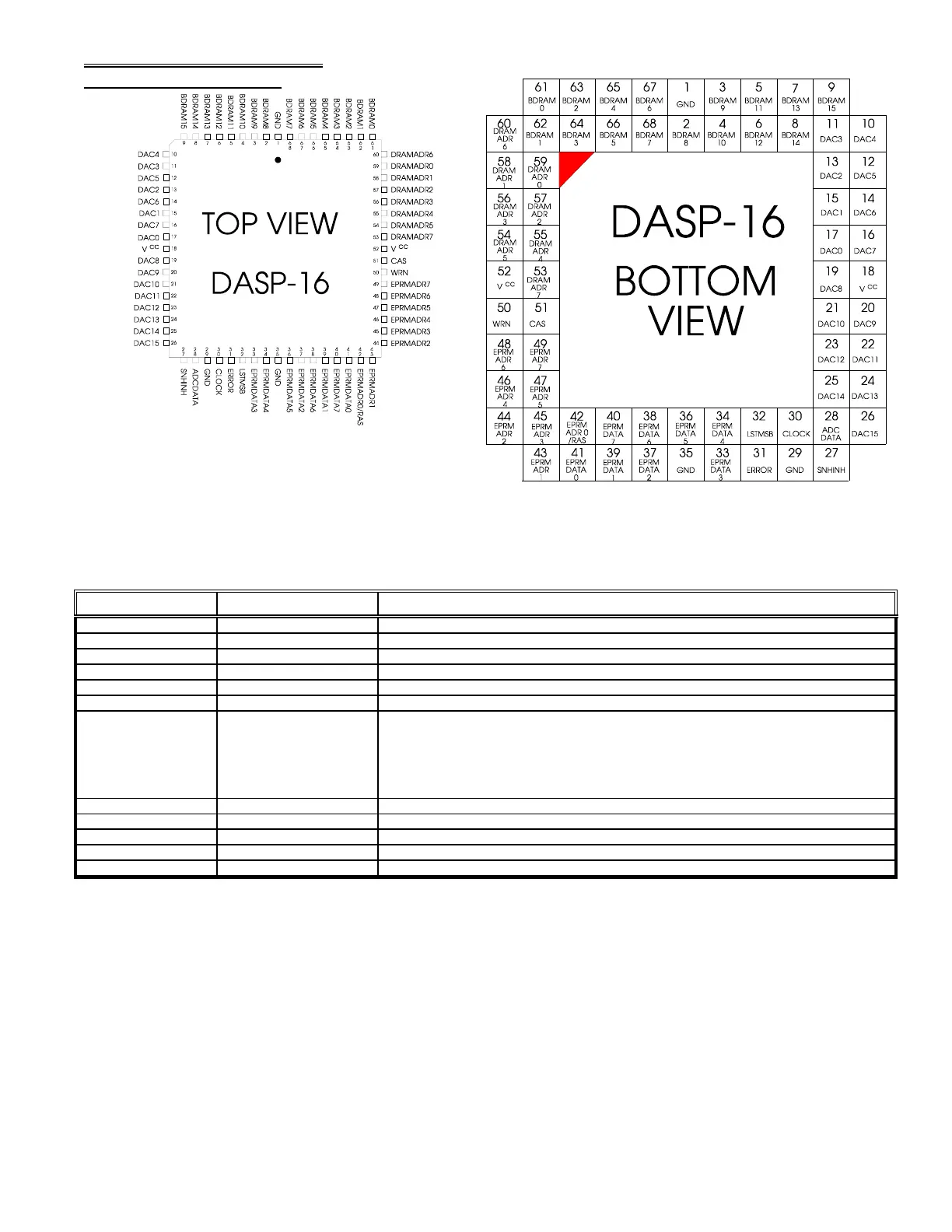
The DASP 16 ASIC
Below is a description of the most important DASP-16 pins.
Pin #(s) Name Function
61-68, 2-11 BDRAM0-15 DRAM Data buss.
10-17, 19-26 DAC0-15 DAC Data outputs.
27 SNHINH
Controls sample and hold circuit timing.
28 ADCDATA
A/D comparison input.
30 CLOCK ASIC Clock input (6MHz for MicroVerb or 8Mhz for MicroVerb II)
31 ERROR
This signal indicates a math overflow condition, and consequently turns on the clip LED circuit.
32 LSTMSB
This signal indicates the last state of the MSB (the sign bit in two's complement math). This signal, in conjunction
with R27, R29, R44, and C17, is used to bias the incoming analog signal slightly positive, or negative, depending
on the result of the last DAC cycle (i.e. if the last DAC cycle started off with a negative value, LSTMSB will be 1,
causing the input to the sample and hold circuit to pull slightly positive. On the next cycle, the reverse will occur).
This reduces any audio pop during the attack portion of the input signal, and allows for a faster response to small
signals.
33-34, 36-41 EPRMDATA0-7 EPROM Data buss.
42-49 EPRMADR0-7 EPROM Address buss.
50 WRN Write ENable line to DRAMs.
51 CAS Column Address Strobe to DRAM.
53-60 DRAMADR0-7 DRAM Address buss.
Diagram 1
Diagram 2