MicroVerb/MicroVerb II Service Manual 1.00 4 3/7/2003
(barring internal leakage ). At this point, the SAR (Successive Approximation Register) in the
ASIC will take over. Starting with the MSB, the SAR will set
the bit, and compare the output of the DAC to the level of
the input sample
capacitor (via
comparator U8). The
results of the
comparison are stored,
and the next most
significant bit is tested.
This process continues
until a value is found for
all 16 bits, and the data
is ready for further
processing by the ASIC.
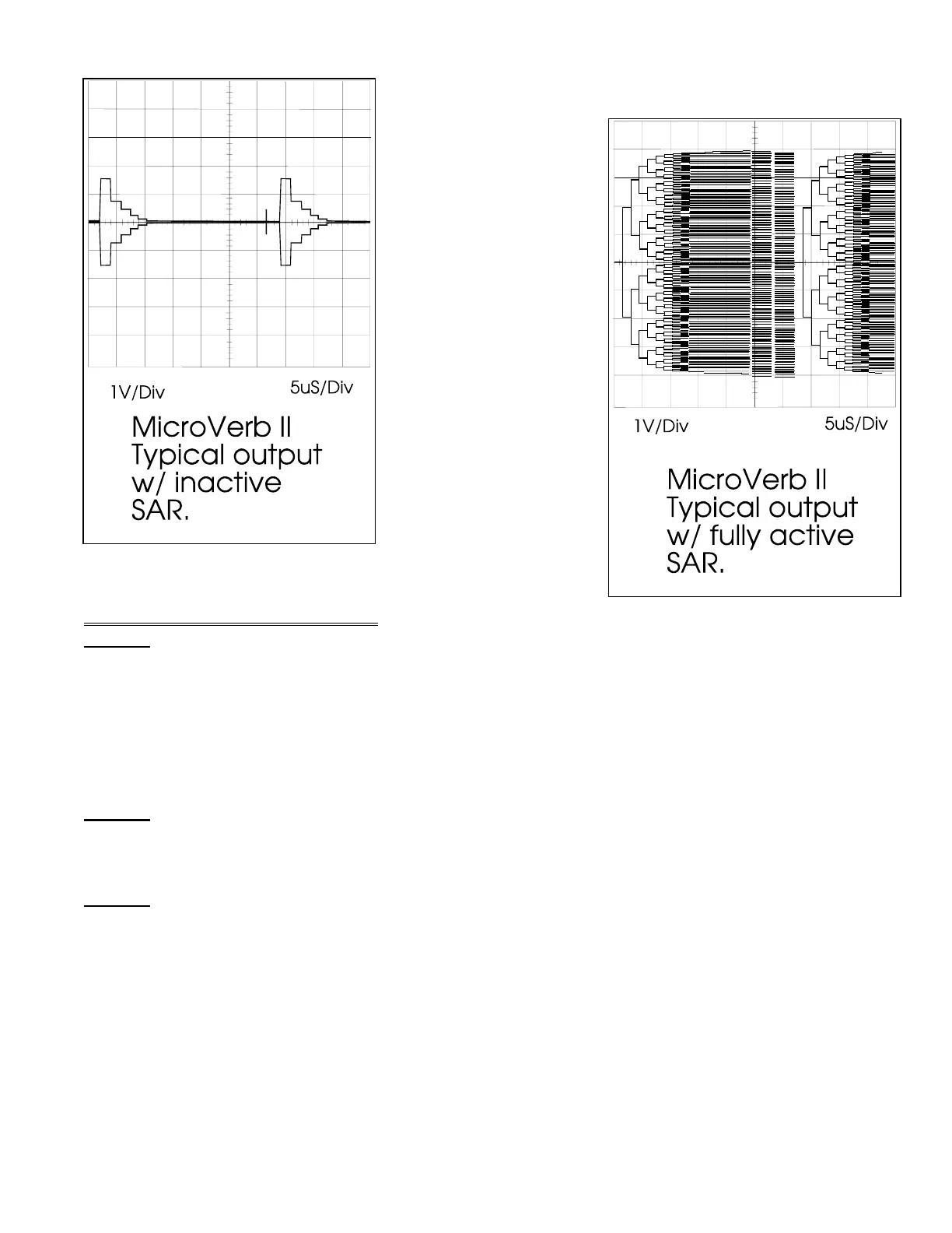
In order to see this
signal properly on the
scope, it will be
necessary to use an
external scope sync
(Use U13 pin 11).
Diagrams 4 and 5 show
typical DAC output
during successive
approximation with no and high input levels respectively.
6.0 Updates and Corrections
6.1
C13
If a blue monoblock capacitor is found in this position, it must be replaced with a 0.1µF
CerDisk or Film capacitor. The reason this is necessary is due to the fact that these capacitors were
found to leak excessively for the circuit (these capacitors are fine for power supply filtering, but
when used as a component in a voltage divider, the excess leakage will cause a significant enough
of a voltage drop to trigger TTL logic). A faulty C13 will cause the LED to indicate an input signal is
present (always green) regardless of input conditions.
6.2
C16
See Section 6.1 for details. A faulty C16 will cause the LED to indicate an overflow (always
red) regardless of input conditions.
6.3
C20
Large Mylar capacitors in this position should be replaced with film capacitors. (again
because of excessive leakage). A failure of this capacitor will cause distorted effects (wet signal).
Diagram 4
Diagram 5