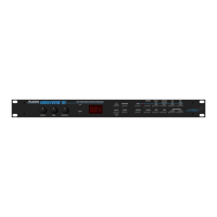
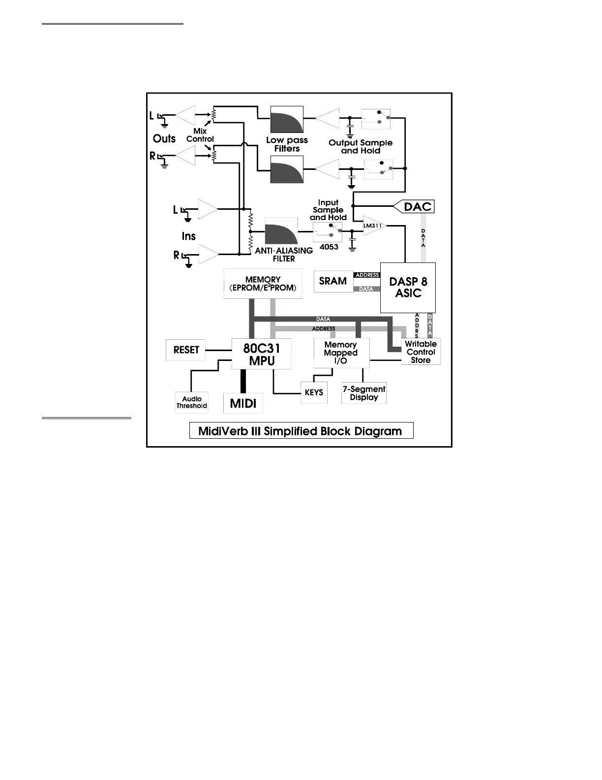
1.0 M3 GENERAL DESCRIPTION
The M3, and other digital effects processors, achieve their results by slicing analog signals
into segments, and then converting them to a numeric value, corresponding to the amplitude of the
signal at that particular instant. These values are then mathematically manipulated, and stored at
various locations in a memory "loop" for eventual playback. By varying the placement and amplitude
of incoming samples, discrete time delays are achieved. When mixed together, and converted back
into analog, these
delays simulate the
reflections associated
with natural reverbs,
and delays, as well
as non natural effects
such as reverse
reverbs, and gated
reverbs. The added
capabilities of an
80C31 micro
c
ontroller allow for
user manipulation
and storage of
algorithm parameters,
as well as effects
such as chorus, and
flange, that require
real-time
manipulation of
algor
ithms. Please
note that there are
several differ
ent
board revisions,
so
differences will be
noticed from unit to
unit.
2.0 POWER SUPPLY
The power
supply begins with
the 9 Volt, A.C.,
adapter. Input from J7 is R.F filtered (or bypassed in some units) by the large torroid and C68. From
there it is split for the +12V, -12V, and +5V rails. The +12V rail consists of a voltage doubler (C69,
C73, and 2 diodes), a filter cap (C81) a 7812 regulator (VR1), and filter capacitors (C7, C72, and
C80). The -12V rail is a "mirror" of the +12V rail, consisting of voltage doubler (C70, C74, and 2
diodes), a filter cap (C83), a 7912 regulator (VR2), and filter capacitors (C6, C40, C71, and C82).
The +5V rail consists of a rectifier diode, filter capacitors (C75-C78, and C84), a 7805 regulator
(VR3), filter capacitor (C85), and many 0.1uF bypass capacitors.
Diagram 1
 Loading...