IMCP0002 Rev.J 5
2 - Installation
2.1 - General requirements & precautions
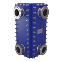
• To allow maintenance and inspection, we recommend leaving a 50 to 120 cm (19 to 48") wide space all around
the Compabloc unit to facilitate panel dismantling.
At the top of the exchanger, it is necessary to have a 100cm (40”) f ree space to allow the possible setting of a
panel-lifting device.
• It is strongly recommended to install the Compabloc on a foundation. Please pay attention in foundation design:
make sure that you have enough space (at least 30 cm) under the bottom bolting of each panel to use tightening
tools in case of maintenance or cleaning. Notice that the panel bolts placed behind flanges may be unaccessible
if the foundation is too close. Please refer to the General Arrangement Drawing when designing foundation.
• Follow good engineering practice both in the design and operation of the plant. Take appropriate precautions to
avoid hydraulic shocks (water hammer), which could damage Compabloc (see Start up section 3.2).
• The connecting pipework should be provided with valves in order to isolate the unit. Valves are essential between
any pump and the Compabloc.
• All valves should have a slow valve action. Flowrates should be increased slowly and gradually during start up
and reduced gradually during shut down.
• Centrifugal pumps are recommended. Do not use piston-type pumps in line with the Compabloc (these generate
repetitive pulsations in flowrate which may cause serious damage to the plate pack).
• Preferably pumps should be installed on the outlet instead of inlet to limit stress on the plate pack when pump
load varies.
• When specifying pumps and heat exchangers, allow ample margins for pressure drop increases above stated
design values. These can be the result of possible variations in fluid properties, flow rates, scaling or deposits on
the heat transfer surfaces.
• When using live steam as heating medium, install a steam trap on the condensate outlet pipe, preferably with
automatic venting of non-condensables.
• Make a check of the torques of the panel bolting before insulating the unit (see para 3.1 for more details) and
piping it.
• When provided with the unit, place the shearing pins in position before fastening the feet on the Compabloc.
• Detach any label fastened to vent and/or drain before connecting.
2.2 – Installation
• Pipework
No specific precaution needs to be taken when connecting the Compabloc. However, if the connection pipework
includes long, straight runs, it is essential to insert correct bends, or expansion devices. Alfa Laval suggests
placing the pipe supports at a maximum of 2 meters (72 in) distance from the unit.
 Loading...
