CONTACT CSI FOR MORE INFORMATION | CSIDESIGNS.COM | SALES@CSIDESIGNS.COM | 417.831.1411
3 Installation
Read the instructions carefully. The valve is supplied as separate parts to facilitate welding.
LKB: for ISO tubes.
LKB-2: for DIN tubes.
LKB-F: with flange connection.
3.3 Welding
S
t
e
p
1
L
K
B
/
L
K
B
-
2
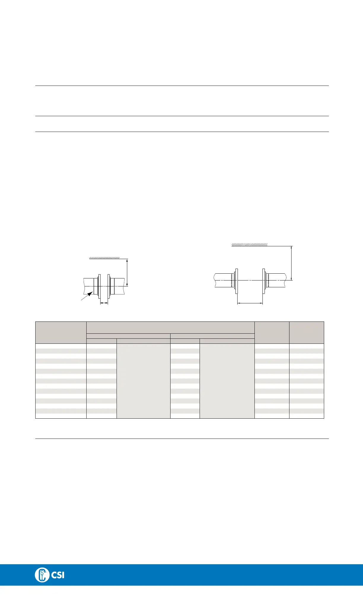
1. Weld the valve body halves into the pipelines.
2. Maintain the minimum clearance (A) so that the actuator can be removed.
3. If welding both valve body halves, ensure that they can be moved axially B
1
m
m
, so that the valve parts can be removed.
4. After welding, assemble the valve according to steps 1-5, chapter 5.3 Assembly of valve - LKB/LKB-2/LKB-LP
L
K
B
-
F
1. Weld the flanges into the pipelines.
2. Maintain the minimum clearances (A and B2) so that the actuator and the valve parts can be removed.
3. After welding, assemble the valve according to steps 1-5, chapter 5.3 Assembly of valve - LKB/LKB-2/LKB-LP
P
r
e
-
u
s
e
c
h
e
c
k
-
L
K
B
/
L
K
B
-
2
/
L
K
B
-
F
Open and close the valve several times to ensure that the valve disc moves smoothly against the seal ring.
P
a
y
s
p
e
c
i
a
l
a
t
t
e
n
t
i
o
n
t
o
t
h
e
w
a
r
n
i
n
g
s
!
L
K
B
L
K
B
-
F
TD 403-088
A
B
1
B
A
2
TD432-002_1
C
a
u
t
i
o
n
!
A
(
m
m
)
Ø
8
5
Ø
1
3
3
S
i
z
e
L
K
L
A
L
K
L
A
-
T
L
K
L
A
L
K
L
A
-
T
B
1
(
m
m
)
B
2
(
m
m
)
1” 245 20 43
1½”
245
20 43
2” 255 20 47
2½”
265
24 46
3” 265 24 59
4” 290 420 37 59
DN25 245 20 43
DN32 245 20 43
DN40 250 20 43
DN50 260 20
47
DN65 270 24 59
DN80 275 27 59
DN100 290 420 27 59
DN125 315 440 30 63
DN250 325
+ 172
(incl. top unit)
445
+ 172
(incl. top unit)
41 79
11

 Loading...