CONTACT CSI FOR MORE INFORMATION | CSIDESIGNS.COM | SALES@CSIDESIGNS.COM | 417.831.1411
3 Installation
Read the instructions carefully and pay special attention to the warnings!
NC = Normally closed.
NO = Normally open.
A/A = Air/air activated.
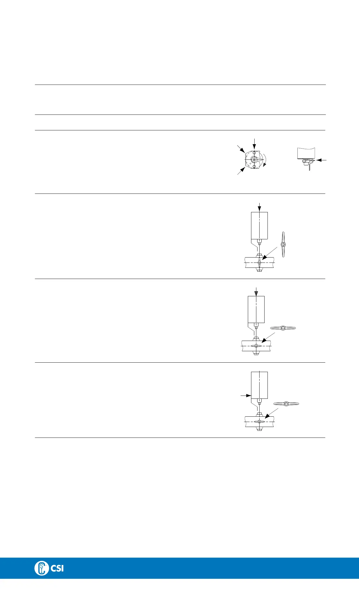
3.4 Fitting actuator/bracket/handle on the valve (optional extras)
S
t
e
p
1
B
r
a
c
k
e
t
/
i
n
d
i
c
a
t
i
o
n
:
1. Fit the bracket as
shown.
2. Fit and tighten t
he screws.
3. Fit the activati
ng ring/indication pin as shown.
Screw for bracket
Bracket
TD 403-121
Drain hole Direction
of rotation
Activating ring/
indication pin
S
t
e
p
2
A
c
t
u
a
t
o
r
/
b
r
a
c
k
e
t
-
N
C
:
1. Ensure that the valve is closed by checking the position of the
groove of the disc stem top.
2. Fit the actuator/bracket in accordance with chapter 5.3
Assembly of valve - LKB/LKB-2/LKB-LP, Step 4.
NC actuator
N
o
p
r
e
s
s
u
r
e
!
TD 403-122
C
l
o
s
e
d
S
t
e
p
3
A
c
t
u
a
t
o
r
/
b
r
a
c
k
e
t
-
N
O
:
1. Ensure that the valve is open by checking the position of the
groove of the disc stem top.
2. Fit the actuator/bracket in accordance with chapter 5.3
Assembly of valve - LKB/LKB-2/LKB-LP, Step 4.
NO actuator
N
o
p
r
e
s
s
u
r
e
!
TD 403-123
O
p
e
n
S
t
e
p
4
A
c
t
u
a
t
o
r
/
b
r
a
c
k
e
t
-
A
/
A
:
1. Ensure that the valve is open by checking the position of the
groove of the disc stem top.
2. Supply compressed air to the actuator.
3. Fit the actuator/bracket in accordance with chapter 5.3
Assembly of valve - LKB/LKB-2/LKB-LP, Step 4.
A/A actuator
A
i
r
p
r
e
s
s
u
r
e
!
O
p
e
n
TD 403-124
12

 Loading...