CONTACT CSI FOR MORE INFORMATION | CSIDESIGNS.COM | SALES@CSIDESIGNS.COM | 417.831.1411
3 Installation
The instruction manual is part of the delivery. Read the instructions carefully.
The items refer to parts list and service kits sections.
The valve is supplied as separate parts as standard (for welding)
The valve is assembled before delivery, if it is supplied with fittings (LKB/LKB-2)
3.1 Unpacking/delivery
S
t
e
p
1
C
A
U
T
I
O
N
Alfa Laval cannot
be held responsible for incorrect unpacking.
C
h
e
c
k
t
h
e
d
e
l
i
v
e
r
y
:
1. Complete valve (see Step 2).
2. Complete actuator, if supplied (see Step 3).
3. Bracket for actuator, if supplied (see Step 3).
4. Complete handle, if supplied.
5. Delivery note.
6. Instruction manual.
S
t
e
p
2
S
t
a
n
d
a
r
d
d
e
l
i
v
e
r
y
o
f
v
a
l
v
e
p
a
r
t
s
:
1. Two valve body halves (1).
2. Valve disc (2) fitted in seal ring (5).
3. Two bushes (3, 4) fitted on the disc stem.
4. A set of screws and nuts (6).
5. Two flanges (7) and two flange seal rings (8), (LKB-F).
Separate part
s for welding
TD 403-102
1 5 24 3
6
1
5
2
4
78
TD 403-285
LKB/LKB-2 LKB-F (only for welding)
S
t
e
p
3
D
e
l
i
v
e
r
y
o
f
a
c
t
u
a
t
o
r
a
n
d
b
r
a
c
k
e
t
:
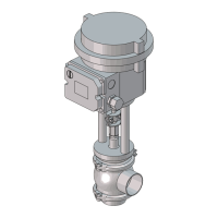
1. Complete actuator with coupling and activating ring (ø85 mm)
or indication pin (ø133 mm).
2. Bracket with screws for the actuator.
3. Mount the water rejector in the actuator
LKLA
ø85mm
Bracket
with screws
LKLA
ø133mm
Water reje
ctor
TD403-103
Coupling
S
t
e
p
4
1. Clean the valve/valve parts for possible packing materials.
2. Clean the handle or the actuator, if supplied.
Handle Valve Actuator
TD 403-090
R
e
m
o
v
e
p
a
c
k
i
n
g
m
a
t
e
r
i
a
l
s
!
S
t
e
p
5
I
n
s
p
e
c
t
i
o
n
!
1. Inspect the valve/valve parts for visible transport damage.
2. Inspect the handle or the actuator, if supplied.
C
a
u
t
i
o
n
!
Avoid damaging the valve/valve parts.
Avoid damaging the handle or the actuator, if supplied.
Hand
le
Valv
e
Actu
ator
TD 403-090
8

 Loading...