CONTACT CSI FOR MORE INFORMATION | CSIDESIGNS.COM | SALES@CSIDESIGNS.COM | 417.831.1411
3 Installation
Read the instructions carefully. The valve has welding ends as standard but can also be supplied with fittings (not LKB-F).
NC = Normally closed.
NO = Normally open.
A/A = Air /air activated.
3.2 General installation
S
t
e
p
1
A
l
w
a
y
s
read the technical data thoroughly.
See chapter 6 Technical data
A
l
w
a
y
s
release compressed air after use.
N
e
v
e
r
touch the coupling between the valve body and the actuator if compressed air is supplied to the actuator.
C
A
U
T
I
O
N
Alfa Laval cannot be held responsible for incorrect installation.
S
t
e
p
2
Avoid stressing the valve.
Pay special attention to:
- Vibrations
- Thermal expansion of the tubes
- Excessive welding
- Overloading of the pipelines
Risk of damage!
TD 403-091
S
t
e
p
3
F
i
t
t
i
n
g
s
:
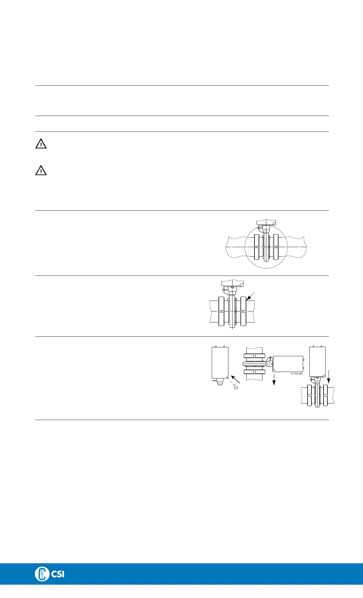
Ensure that the connections are tight.
TD 403-092
R
e
m
e
m
b
e
r
s
e
a
l
r
i
n
g
s
!
S
t
e
p
4
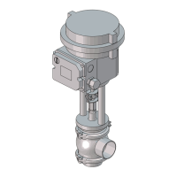
P
o
s
i
t
i
o
n
o
f
a
c
t
u
a
t
o
r
:
Position the water rejector on the actuator correctly.
(The actuator can be installed in any position).
T
u
r
n
t
h
e
v
e
n
t
i
l
a
t
i
o
n
o
p
e
n
i
n
g
d
o
w
n
w
a
r
d
s
!
TD 403-286
I
m
p
o
r
t
a
n
t
!
9

 Loading...