Do you have a question about the Alfa Network A1930 and is the answer not in the manual?
Details on attaching the under cover and placing the machine head onto the table.
How to position the pedal and straighten the motor control lever and connecting rod.
Procedure to adjust the pedal's tilt by changing the length of the connecting rod.
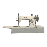
This document is an instruction manual for the ALFA Model A1930, a high-speed computer flat sewing machine. It provides comprehensive information on its specifications, installation, operation, and maintenance.
The ALFA A1930 is designed for both light to medium-weight materials and medium to light-heavy materials. For light to medium-weight materials, it boasts a maximum sewing speed of 5000 rpm and a maximum stitch length of 5 mm. It uses DBX1 #9-18 (#14) needles. When working with medium to light-heavy materials, the machine operates at a maximum sewing speed of 4000 rpm, offers a maximum stitch length of 7 mm, and utilizes DBX1 #20-23 (#14) needles. The presser foot lift is standard at 10 mm, and the machine uses White Oil 10 for lubrication.
Before operation, several safety precautions and setup procedures are emphasized. Users are warned to observe basic safety measures, read all instructions, and ensure the machine conforms to local safety standards. All safety devices must be in place, and only appropriately trained operators should use the machine. Safety glasses are recommended. Crucially, the power switch must be turned off or the power plug disconnected before threading needles, replacing parts (like needles, presser feet, throat plates, feed dogs, etc.), or performing any repair work. This also applies when leaving the workstation unattended. In case of contact with oil or grease, immediate washing and medical consultation are advised. Tampering with live parts is prohibited. Repairs, remodeling, and adjustments should only be performed by trained technicians using designated spare parts. General maintenance and electrical component repairs also require skilled personnel. If pneumatic parts are involved, the air compressor must be detached, and compressed air supply cut off before maintenance. The machine requires periodic cleaning and proper grounding. An appropriate power plug, installed by electric technicians, must be connected to a grounded receptacle. The manual also highlights the importance of not modifying the machine without adhering to safety rules, as the manufacturer assumes no responsibility for damage resulting from such alterations. Warning hints are marked with specific symbols indicating danger of injury or items requiring special attention.
For safe operation, users are explicitly warned against opening the electrical box or touching internal components to avoid electrical shock. To prevent personal injury, the machine should never be operated without the belt cover, finger guard, or other safety devices. Fingers, head, and clothes must be kept away from the handwheel, V-belt, and motor during operation. Hands should never be placed under the needle when turning on the power or operating the machine, nor should fingers be inserted into the thread take-up cover. Due to the high-speed rotation of the hook, hands must be kept clear during operation, and power must be turned off when replacing the bobbin. Care must be taken to avoid fingers getting caught when tilting/raising the machine head. To prevent abrupt starts, the power should be turned off when tilting the machine head. If equipped with a servo-motor, which is silent when at rest, the power must still be turned off to prevent unexpected starts. Operating the machine without a grounded power supply wire is an electrical shock hazard. The power switch must be turned off before connecting or disconnecting the power plug.
Before initial operation, the machine should be thoroughly cleaned to remove transportation dust and then oiled. The power plug must be properly connected to the correct voltage type. The sewing machine's handwheel should rotate counterclockwise; reverse rotation should be avoided.
Installation involves placing the oil pan on the machine table groove, fixing rubber seats on the operator's side with nails, and cushion seats on the hinged side with adhesive. The oil pan is then placed on these seats. The machine head is fitted by inserting the hinge into the machine bed opening and then placing it on the rubber hinge and cushions.
Adjusting the height of the knee lifter is crucial for comfortable operation. The standard presser foot lift is 10 mm, adjustable up to 13 mm using the knee lifter adjust screw. However, if the presser foot lift exceeds 10 mm, it's essential to ensure the needle bar's bottom end in its lowest position does not hit the presser foot.
Installing the thread stand involves assembling the unit, inserting it into the machine table hole, and tightening a locknut. The power cord for ceiling wiring should be passed through the spool rest rod.
Lubrication is vital for machine longevity. The oil pan should be filled with Machine Oil up to the HIGH mark. When the oil level drops below the LOW mark, it must be refilled. After lubrication, splashing oil should be visible through the oil sight window, indicating adequate lubrication. The amount of splashing oil is not related to the total lubricating oil amount. For new machines or those unused for extended periods, a break-in period of 10 minutes at 3,000 to 3,500 rpm is recommended.
Adjusting the amount of oil (oil splashes) in the hook requires extreme caution due to the high-speed operation. The oil splash amount is confirmed by placing a paper under the hook for five seconds while the machine runs. The oil surface height in the reservoir should be between "HIGH" and "LOW." The oil amount can be adjusted using a screw on the hook driving shaft front bushing: turning it in the "+" direction increases oil, and in the "-" direction decreases it. After adjustment, the machine should run idle for 30 seconds to recheck the oil amount. The manual provides samples of appropriate oil splash amounts (1 mm for small, 2 mm for large), noting that too little oil can seize the hook, and too much can stain the sewing product.
Attaching the needle also requires turning off the power. A proper needle size should be chosen based on thread count and material type. The handwheel is turned to bring the needle bar to its highest point. Screw 2 is loosened, and needle 1 is held with its intended part A facing right (direction B). The needle is inserted until it goes no further, then screw A is tightened. The long groove of the needle must face left (direction d).
Setting the bobbin into the bobbin case involves passing the thread through slit A and pulling it in direction B, ensuring it passes under the tension spring and exits the notch. The bobbin should rotate in the direction of the arrow when the thread is pulled.
Adjusting the stitch length is done via the operation panel: "+" increases needle widening, and "-" decreases pitch.
Presser foot pressure is adjusted by loosening nut 2, then turning presser spring regulator 1 clockwise (direction A) to increase pressure or counterclockwise (direction B) to decrease it. After adjustment, nut 2 is tightened. For general fabrics, the standard height of the presser spring regulator is 29 to 32 mm.
The hand lifter allows the presser foot to be lifted by turning it in direction A and returns to its original position when turned down in direction B.
Adjusting the height of the presser bar requires turning off the power. Setscrew 1 is loosened to adjust the presser bar height or presser foot angle, then securely tightened after adjustment.
Threading the machine head is done with the needle bar at its highest position, following the illustrated order.
Thread tension involves two adjustments. For needle thread tension, turning tension nut No.1 clockwise (direction A) shortens the thread remaining on the needle after trimming, while counterclockwise (direction B) lengthens it. Turning tension nut No.2 clockwise (direction C) increases needle thread tension, and counterclockwise (direction D) decreases it. For bobbin thread tension, turning tension adjust screw clockwise (direction E) increases tension, and counterclockwise (direction F) decreases it.
The thread take-up spring has two adjustable aspects. To change its stroke, loosen setscrew 2, then turn tension post 3 clockwise (direction A) to increase stroke or counterclockwise (direction B) to decrease it. To change its pressure, loosen setscrew 2 and remove thread tension (asm) 5, then loosen setscrew 4. Turning tension post 3 clockwise (direction A) increases pressure, and counterclockwise (direction B) decreases it.
Adjusting the thread take-up stroke also requires turning off the power. For heavy-weight materials, thread guide 1 is moved left (direction A) to increase thread pulled out. For light-weight materials, it's moved right (direction B) to decrease thread pulled out. Normally, thread guide 1 is aligned with the center of the screw.
The needle-to-hook relationship is critical and requires power to be off. First, the needle bar height is adjusted by turning the handwheel to bring the needle bar to its lowest point, then loosening setscrew 1. For a DB needle, marker line A on needle bar 2 is aligned with the bottom end of needle bar lower bushing 3, then setscrew 1 is tightened. For a DA needle, marker line C is used similarly. Next, the hook position is adjusted. Loosen the three hook setscrews. For a DB needle, turn the handwheel and align marker line B on the ascending needle bar with the bottom end of needle bar lower bushing 3. For a DA needle, marker line D is used. After these adjustments, hook blade point E is aligned with the center of needle 4, ensuring a clearance of 0.04 mm to 0.1 mm between the needle and hook, then the hook setscrews are securely tightened. Incorrect clearance can damage the hook blade or cause stitch skipping.
Adjusting the height of the feed dog involves turning off the power. Loosen screw 2 of crank 1, move the feed bar up or down, then securely tighten screw 2.
Adjusting the tilt of the feed dog also requires turning off the power. The standard (horizontal) tilt is achieved when marker dot A on the feed bar shaft aligns with marker dot B on feed rocker C. To tilt the feed dog front up (to prevent puckering), loosen the setscrew and turn the feed bar shaft 90° in the direction of the arrow. To tilt the feed dog front down (to prevent uneven material feed), turn the feed bar shaft in the opposite direction. Note that adjusting the feed dog tilt will change its height, requiring a check after adjustment.
Adjusting the feed timing is another critical step that requires the power to be off. Loosen screws 2 and 3 in feed eccentric cam 1. Move the cam in the direction of the arrow or opposite, then firmly tighten the screws. For standard adjustment, the top surface of the feed dog and the top end of the needle eyelet should be flush with the throat plate when the feed dog descends. To advance feed timing (prevent uneven material feed), move the cam in the direction of the arrow. To delay feed timing (increase stitch tightness), move the cam in the opposite direction. Moving the cam too far can cause needle breakage.
The pedal adjustment involves installing the connecting rod and adjusting the pedal angle. For installation, move pedal 3 right or left to straighten motor control lever 1 and connecting rod 2. To adjust the angle, loosen adjust screw 4 and adjust the length of connecting rod 5.
Pedal operation is described in four steps: lightly depressing the front part of the pedal (B) results in low sewing speed; further depressing (A) results in high sewing speed (after automatic reverse feed stitching, if preset). Releasing the pedal to its original position stops the machine (with the needle up or down). Fully depressing the back part of the pedal (C) trims threads. If an auto-lifter is present, an additional step occurs between stopping and thread trimming: lightly depressing the back part lifts the presser foot, and further depressing actuates the thread trimmer.
The one-touch type reverse feed stitching mechanism allows reverse stitching by pressing button 1. The machine stitches in reverse as long as the button is held and resumes normal stitching when released. The height of switch lever 1 can be adjusted for easy operation.
The electronic clip wire is described as having two parts: electronic clip wire 1 and electronic clip wire 2, which opens as 1 mm.
Disassembling the operation panel involves using a needle to open points a, b, c, A, B, then removing the panel. Reassembly follows the reverse order. All these steps require the power to be off to prevent accidents.
| Brand | Alfa Network |
|---|---|
| Model | A1930 |
| Category | Sewing Machine |
| Language | English |