Do you have a question about the ALIBI ALI-NVR5316P and is the answer not in the manual?
Indicator lights for power, HDD activity, and network status.
Ports for connecting external USB devices like mice or hard drives.
Half-duplex terminations for RS-485 devices.
Connection for a controller and cascading devices.
Connect up to 16 alarm inputs and 4 alarm outputs.
RS-232, VGA, and HDMI connectors.
RCA audio, RS-485, LAN, and PoE ports.
Power connector, ON/OFF switch, and ground terminal.
USB 3.0 port and eSATA interface for storage.
Describes functions of left-click, right-click, double-click, and scroll wheel.
Alphanumeric, numeric, and symbol keyboards for input.
Connect up to 16 alarm inputs to the RS-485/Alarm IN/OUT connectors.
Connect 4 alarm outputs, with jumper options for DC/AC loads.
Diagram and instructions for connecting DC loads to alarm outputs.
Use an external relay for safety when connecting AC loads.
Connect monitor via HDMI/VGA and plug in USB mouse.
Connect LAN cable and power cord to NVR.
Plug camera Ethernet cables into NVR PoE ports.
Turn on NVR and monitor to begin setup.
Initial screen to activate the NVR and set admin password.
Configure GUID export, unlock pattern, and security questions.
Set system date, time, time zone, and NTP for accurate timestamps.
Configure network settings, including DHCP or static IP.
Initialize connected HDDs for storage use.
Discover, activate, and add network cameras to the system.
Set up Alibi Connect, DDNS, and stream encryption.
Modify admin password and network port numbers.
Enter password or use unlock pattern to log in.
Steps to safely shut down the NVR via the Live View screen.
Details on IP video input channels and two-way audio.
Bandwidth, remote connections, and recording resolution.
Specifications for CVBS, VGA, and HDMI outputs.
Supported decoding formats and resolutions.
Network protocols and management features.
SATA and eSATA interface details for storage.
Serial, USB, and Alarm I/O interfaces.
PoE interface specifications and power output.
Power supply, consumption, temperature, and dimensions.
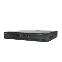
The ALIBI™ ALI-NVR5316P is an Embedded Network Video Recorder (NVR) designed for surveillance systems, offering a range of features for video recording, management, and remote access. This quick setup guide provides essential instructions for initial setup and use, while a more comprehensive user manual details its extensive capabilities.
The NVR serves as the central hub for a surveillance system, capable of connecting to and managing up to 16 IP cameras. It records video streams, stores them on Hard Disk Drives (HDDs), and provides various interfaces for monitoring, control, and network integration. The device supports Power over Ethernet (PoE) for its camera channels, simplifying installation by providing both power and data connectivity through a single Ethernet cable.
The front panel includes status indicators for power, HDD activity, and network connection. The power indicator is green when the unit is on and red when power is available but the unit is off. The HDD indicator blinks red during data read/write operations, and the TX/RX indicator blinks green when the network connection is active. Two USB ports are available on the front for connecting peripheral devices like a mouse or external HDD.
The back panel offers a comprehensive set of connectors:
Upon first power-on or factory reset, the NVR enters an "Inactive" state. The initial configuration wizard guides the user through activation and essential settings:
A standard 3-button USB mouse can be plugged into either the front or back panel USB connector.
The NVR features on-screen keyboards for text and numerical entry, appearing when a field requires input. There are alphanumeric, numeric, and symbol keyboards. Control keys toggle functions like uppercase/lowercase and switching between keyboard types.
The NVR supports up to 16 alarm inputs and 4 alarm outputs.
To shut down the recorder, open the Live View screen, click the Power Off icon, and then select "ShutDown" from the pop-up window.
After initial setup, if an unlock pattern was configured, the unlock screen appears. Users drag the mouse cursor across the selected pattern to log in. Otherwise, the Welcome screen appears, requiring the admin password for login.
The NVR monitors the status of installed HDDs. If an HDD shows an "Uninitialized" status, it must be initialized to become usable. This process erases all data on the disk.
Users can refer to the ALIBI™ Embedded Network Video Recorder Firmware V4.1.50 (or later) User Manual for detailed information on the NVR's capabilities. Additional documentation and software are available at AlibiSecurity.com/Resources.
The NVR supports remote access through its LAN connection and can transmit alerts and emails to external servers. Configuring network settings, including DHCP or fixed IP, is crucial for reliable remote access. The Alibi Connect service and DDNS features further facilitate remote connectivity.
| Model | ALI-NVR5316P |
|---|---|
| Maximum Bandwidth | 160 Mbps |
| IP Camera Input | 16 |
| Video Output | 1 HDMI, 1 VGA |
| Maximum Resolution | 8MP |
| Resolution | 8MP (3840x2160) |
| Storage Capacity | Up to 10TB capacity for each HDD |
| Network Interface | 1 RJ-45 10/100/1000 Mbps self-adaptive Ethernet interface |
| Power Supply | 100-240V AC, 50/60Hz |
| PoE Ports | 16 |
| PoE Standard | IEEE 802.3 af/at |
| Audio Output | 1 |
| USB Interface | 2x USB 2.0 |
| Operating Temperature | -10°C to +55°C |
| Video Compression | H.265+/H.265/H.264+/H.264 |