Do you have a question about the ALIBI ALI-NVR5332P and is the answer not in the manual?
Describes the function and color of the NVR's status LEDs for power and activity.
Details the Universal Serial Bus ports for connecting external devices like mice or HDDs.
Explains the DB9 (male) connector for RS-232 serial devices.
Describes VIDEO OUT (VGA, HDMI1, 2) and eSATA ports for display and storage.
Details the RCA connectors for Line level audio input and output.
Covers RS-485, Alarm IN (1-16), and Alarm OUT (1-4) connections.
Describes the power connector, ON/OFF switch, and ground terminal.
Details LAN interface and USB 3.0 ports for network and device connectivity.
Explains the 24 internal Ethernet ports providing Power over Ethernet (PoE) to cameras.
Summarizes mouse actions like right-click, single-click, and double-click effects in live view.
Instructions for connecting up to 16 alarm inputs to the NVR's RS-485, Alarm IN/OUT connector.
Details connecting 4 alarm outputs, including jumper configuration for AC/DC loads.
Provides a diagram and guidelines for connecting DC loads to alarm outputs.
Steps for connecting a monitor via HDMI/VGA and a mouse via USB.
Instructions for connecting the NVR to the local area network via RJ45 LAN connector.
Details connecting the power cord to the NVR and a UPS or surge protector.
Connecting camera LAN cables to NVR PoE ports and other network cameras.
Steps to power on the NVR and its connected monitor.
Steps to create a strong administrator password using the on-screen keyboard.
Option to enter an email address for password recovery.
Feature to create a GUID file on a flash drive for password recovery.
Setting up security questions for password recovery.
Setting a default password for cameras connected to the NVR.
Setting the local time zone and date format for accurate timestamps.
Manually setting the system date and time or enabling NTP for automatic updates.
Explains DHCP default and how to configure fixed network settings and DNS.
Details IP address, subnet mask, default gateway, and DNS server configuration.
Process to activate network cameras discovered on the local network.
Steps to add activated cameras to the NVR surveillance system.
Enabling Alibi Witness 2 smartphone app access and configuring its settings.
Configuring Dynamic Domain Name System for simplified remote recorder access.
Securing video streams for live view, playback, and downloads using encryption.
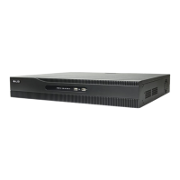
This document describes the ALI-NVR5332P Embedded Network Video Recorder, a device designed for surveillance systems. It provides instructions for initial setup, configuration, and operation, covering both hardware connections and software settings.
The ALI-NVR5332P is a network video recorder (NVR) that supports up to 32 channels, allowing it to manage and record video from multiple IP cameras. It is designed for continuous, schedule-based, alarm-triggered, motion detection, POS, and event-based recording. The NVR supports various compression formats, including H.265+, H.265, H.264+, and H.264, to optimize storage and bandwidth. It offers a recording performance of 320 Mbps and a remote viewing output capacity of 256 Mbps, accommodating up to 128 remote connections. The device runs on an Embedded Linux operating system and includes password protection for security.
Video and Audio:
Storage and Connectivity:
Physical and Environmental:
Protocols: IPv4, TCP/IP, UDP, HTTP, UPnP, RTSP/RTP/RTCP, SMTP, FTP, DHCP, NTP, DNS, ONVIF, HTTP multipart.
Initial Setup and Activation: The NVR guides users through an initial setup wizard upon first power-on or factory reset. This "Inactive" state requires the creation of an admin user password for the recorder and cameras. The wizard then facilitates basic settings like date and time, network configuration, camera setup, and HDD initialization.
User Interface and Control:
Security Features:
Network Configuration:
Camera Management:
Storage Management:
Firmware Updates: The document refers to a user manual for detailed procedures on updating the NVR's firmware to the latest version (V4.21.005 or later).
Alarm Output Configuration:
Troubleshooting:
Supplied Accessories: The NVR comes with a Quickstart Guide, USB Mouse, 110 Vac Power Cord, HDD SATA cables, Rack Mount Ears, 6ft HDMI Cable, and 6ft Ethernet Patch Cord, facilitating initial setup and maintenance.