3 www.Observint.com
© 2018 Observint Technologies. All rights reserved.
Step 4. Using the Wizard for basic configuration setup
When the NVR is rst powered on, or reset to its Factory default conguration, It is in an “Inactive” state, which means that it is not it doesn’t
have an admin user password for the recorder or cameras, and it is not congured to record video or log system status messages. The initial
conguration screen enables you to activate the recorder.
After activating the recorder and conguring its security options, a conguration Wizard will open. The Wizard helps you to easily congure
the recorder for its basic settings, including date and time, network conguration, network cameras, HDD initialization, etc.
1. Power on the NVR. Normally, an Alibi logo splash screen appears within 2 minutes. The following screen is used to activate the
recorder.
In the screen above:
a. Click on the Create New Password eld, and then enter a unique password using the pop-up virtual keyboard. Follow the
guidelines in the Note at the bottom of the screen. Always use a password that will produce a “Strong” rating (green indicator
in the status bar).
b. Enter the same New Password in the Conrm New Password eld.
c. Select or deselect the checkboxes to:
Export GUID: This feature enables you to create a GUID le and save it to a ash drive for logging back into the NVR if you loose
your admin password.
Enable Unlock Pattern: This option allows you to login by dragging the mouse across a 3 x 3 matrix to quickly login to your
admin account.
Security Question Conguration: If you loose your password, this option enables you to login by responding correctly to
security questions you setup.
d. Enter a password in the Create Channel Default Password eld. This will become the default password of the admin user
of cameras plugged into the internal switch on the backpanel of the NVR. Follow the guidelines in the Note below this eld.
2. Click the OK button to continue. If passwords were setup properly in the Activation menu, an Note window will appear showing the
NVR is now “activated.” Leave the Note window open.
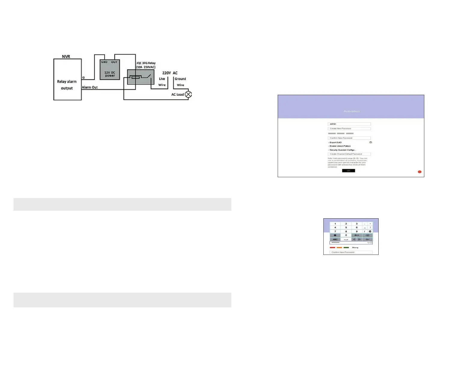
AC load alarm output circuits
To connect an AC load to an alarm output, a jumper, associated with the output on the alarm termination PC board, (within the chassis), must
be removed. These jumpers shunt pin pairs J1, J2, J3, and J4 for alarm outputs 1, 2, 3, 4 respectively. Use an external relay for safety.
Step 2. Install a monitor, mouse, power
For the following steps, refer to the back panel photo above for the location of connectors.
1. Install and setup your monitor in accordance with the instructions provided with the monitor. Do not power it on at this time.
2. Cable the HDMI or VGA connector to your monitor’s VGA or HDMI input. The HDMI interface provides the best performance.
3. Plug the mouse into the USB connector on the front or back of the NVR.
4. If you plan to access your NVR remotely, or congure your NVR to transmit alerts, email, etc. to external servers, plug a drop cable from
your local area network (LAN) into the RJ45 LAN connector on the back of the NVR.
5. Connect the power cord to the power connector on the back panel of the NVR, and then into a UPS (preferred) or surge protector.
NOTE
Do not power on the NVR at this time.
Step 3. Connecting it together – initial system setup
1. Plug the LAN cables from the cameras into the POE RJ45 connectors on the back of the NVR.
If other cameras to be monitored by the NVR will network to it through the LAN, plug their Ethernet cables into a switch (router) on
the LAN and power on those cameras. (Power to other cameras on the LAN may be provided through a PoE switch if the camera is PoE
capable, or through a separate cable and power adapter).
2. Power on the NVR using the power on / o (I / O) switch on the back panel.
3. Power on the monitor.
NOTE
Some monitors have multiple inputs such including VGA ,HDMI, BNC, etc. If you are using this kind of monitor, congure your monitor to
display the input connected to your NVR (HDMI or VGA).