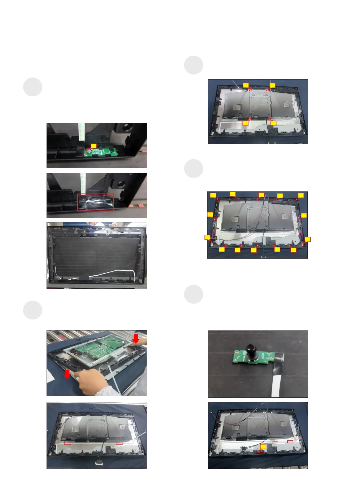
5. Disassembly and Assembly Procedures
Use a Philips-head screwdriver to tighten 14pcs
screws for locking the middle bezel with the panel
module, then paste 2pcs shading mylar tape to cover
the two screws holes of the middle frame.
(No.1~14 Screw size= M3x5, Torque=3~4kgfxcm)
S10
Take 1pcs power key board with key cable and 1pcs
middle frame, and then locate the power key board to
the specific position of the middle frame. Put the unit
into a fixture, use a Philips-head screwdriver to
tighten 1pcs screw for locking the power key board
with the middle frame, then cover the power key
board with 1pcs black mylar tape.
(No.1 Screw size= M2x2.4, Torque=0.8±0.2kgfxcm)
S8
Assemble the middle frame with the panel module.
Tear off 2pcs tape papers on the back of the power
key cable, then fix the power key cable on the back
of the panel with tapes on the back of the cable.
S9
Take 1pcs joystick board and 1pcs cap, and
assemble the cap with joystick key, then locate the
joystick board unit into the hooks of the middle frame.
Use a Philips-head screwdriver to tighten 1pcs screw
for locking the joystick board with middle frame, then
tear off 2pcs tape papers on the back of the key
cable, then fix the cable on the back of the panel.
(No.1 Screw size= M3x6, Torque=2~2.5kgfxcm)
S11
2
3
4
1
(No.1~4 Screw size= M3x2.6, Torque=3~4kgfxcm)
Use a Philips-head screwdriver to tighten 4pcs
screws for locking the bracket with the panel.
1
10
3
6
7
1
9
2
5
8
12
13
4
14
11
1
S12