5. Disassembly and Assembly Procedures
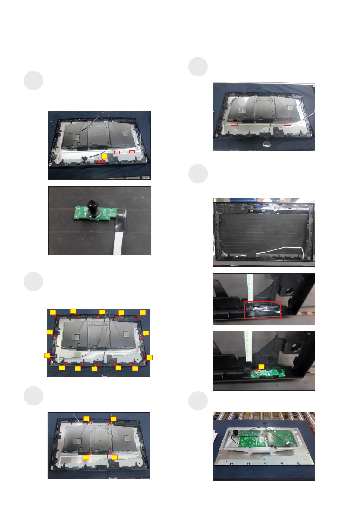
S10
S9
S11
Use a Philips-head screwdriver to remove 1pcs
screw for unlocking the joystick board with middle
frame, then release the key cable by tearing off 2pcs
tapes, then release the joystick board from the hooks
of the middle frame.
(No.1 Screw size= M3x6, Torque=2~2.5kgfxcm)
1
Use a Philips-head screwdriver to remove 14pcs
screws for unlocking the middle bezel with the panel
module, then tear off 2pcs shading mylar tape for
uncovering the two screws holes of the middle frame.
(No.1~14 Screw size= M3x5, Torque=3~4kgfxcm)
10
3
6
7
1
9
2
5
8
12
13
4
14
11
2
3
4
1
Use a Philips-head screwdriver to remove 4pcs
screws for unlocking the bracket with the panel.
(No.1~4 Screw size= M3x2.6, Torque=3~4kgfxcm)
Tear off 2pcs tapes on the back of the power key
cable, then lift up the middle bezel and remove the
middle bezel.
(No.1 Screw size= M2x2.4, Torque=0.8±0.2kgfxcm)
Put the middle frame into a fixture jip, then tear off
the mylar tape, and then use a Philips-head
screwdriver to remove 1pcs screw for unlocking the
power key board with the middle bezel.
S8
S6
S7
1
Lift up the bracket chassis module and put the
bracket chassis module on a protective cushion.