5. Disassembly and Assembly Procedures
S15
S16
S13
S14
S17
(No.1 screw size=M3x6, Torque=4±0.5kgfxcm)
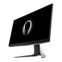
Take 1pcs USB sub board, 1pcs connective cable
and 1pcs FFC cable. Connect the two cables to the
connectors of the USB sub board, paste 1pcs
conductive foam on the back of USB sub board,
then locate the USB sub board into the hooks of
the middle frame. Use a Philips-head screwdriver to
tighten 1pcs screw for locking the USB sub board
with the middle frame. Connect the USB sub cable
to the USB main board, then connect the EDP cable
to the panel connector.
1
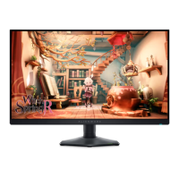
Locate the panel lamp cable into the hooks of the
middle frame, then plug the cable to the connector of
the panel, then cover the panel lamp cable with 1pcs
shading mylar tape.
Connect the power key cable and joystick key
cable to the connectors of the board, then paste
1pcs aluminum foil on the specific position to fix the
cables and EDP connectors.
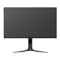
Take 1pcs rear cover close to the panel unit, then
put down the rear cover and push the rear cover
for mechanisms engagement.
Use a Philips-head screwdriver to tighten 4pcs
screws for locking the rear cover with the assembled
unit.
(No.1~4 screw size=M4x10; Torque=9±0.5kgfxcm)
2
3
4
1
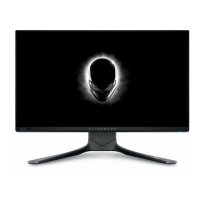
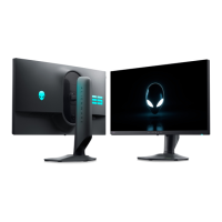
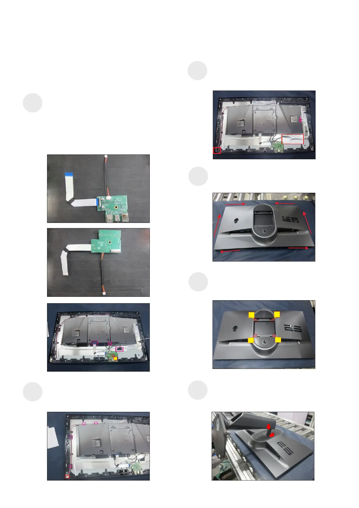
Take a stand base close to the monitor. Fit the two
tabs on the upper part of the stand into the grooves on
the back of the monitor, and then lower the stand so
that the monitor mounting area snaps onto the stand.
S18