5. Disassembly and Assembly Procedures
5.1 Disassembly Procedures:
Tool Required:
List the type and size of the tools that would typically can be
used to disassemble the product to a point where components
and materials requiring selective treatment can be removed.
Tool Description:
- Screwdriver(Phillip head) #1
- Screwdriver(Phillip head) #2
- Penknife
- Soldering iron and absorber
NOTE:
This “Disassembly and Assembly Procedures” is for EMEA only,
not for other regions. Please note that Dell will deem warranty void
if any disassembly is done on the monitors.
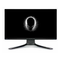
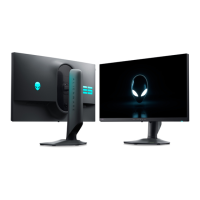
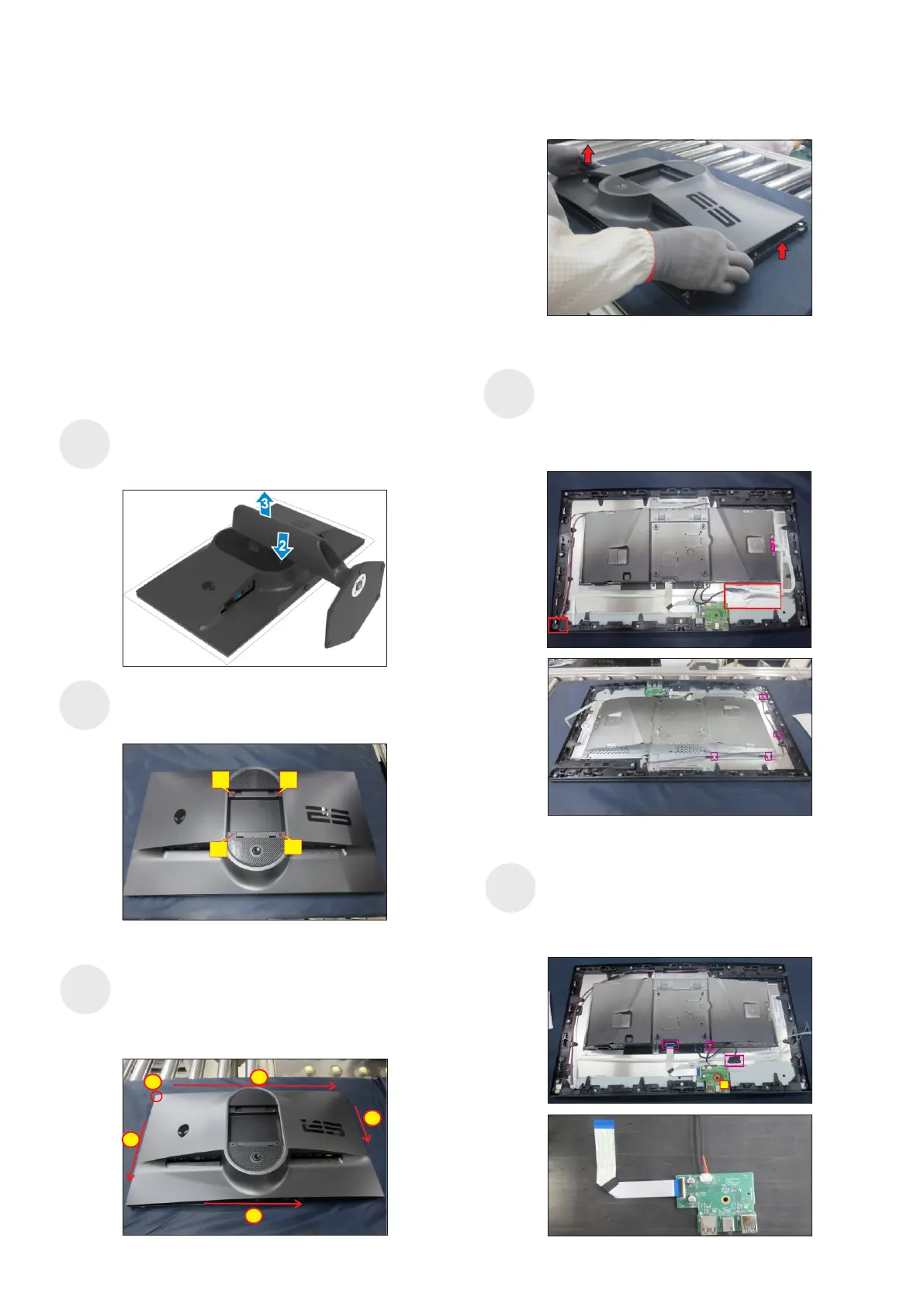
Remove the monitor stand base:
2. Press and hold the stand-release button.
3. Lift the stand up and away from the monitor.
1. Place the monitor on a soft cloth or cushion.
Wedge your fingers between the rear cover and the
middle bezel on the corners of the top side of the
monitor to release the rear cover, then use one hand
to press the middle bezel, the other hand to pull up
carefully the rear cover in order of arrow preference
for unlocking mechanisms of rear cover.
screws for unlocking mechanisms.
Use a Philips-head screwdriver to remove four
(No.1~4 screw size=M4x10; Torque=10~11kgfxcm)
S3
S2
S4
2
3
4
1
Remove the rear cover, then tear off 1pcs aluminum
foil for uncovering the EDP connector, then
disconnect power key cable and joystick key cable
away from the connectors of the board. Tear off 1pcs
shading mylar, then disconnect the panel lamp
connector, then release the cable from the hooks.
4
3
2
3
1
S1
(No.1 screw size=M3x6, Torque=4±0.5kgfxcm)
Disconnect EDP cable from the panel connector,
then disconnect two USB cable from the connector
of the board. Use a Philips-head screwdriver to
remove one screw for unlocking the USB sub board
unit, then release the USB sub board unit.
S5
1