5. Disassembly and Assembly Procedures
Take 1pcs power board, then connect the AC wire to
the connector of the power board, then turn over a
power board and put it into the bracket chassis.
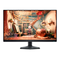
Place a bracket chassis base on a protective
cushion, then paste 3pcs Silicon sheet on the
correct positions as the picture below shown, then
assemble 1pcs AC outlet with the bracket.
5.2 Assembly Procedures:
S2
S1
S3
S5
Take 1pcs interface board, connect 1pcs EDP cable,
1pcs panel lamp cable and 1pcs USB connective
cable to the connectors of the interface board, then
connect the cable of the power board to the interface
board, then turn over and locate it into the bracket.
S7
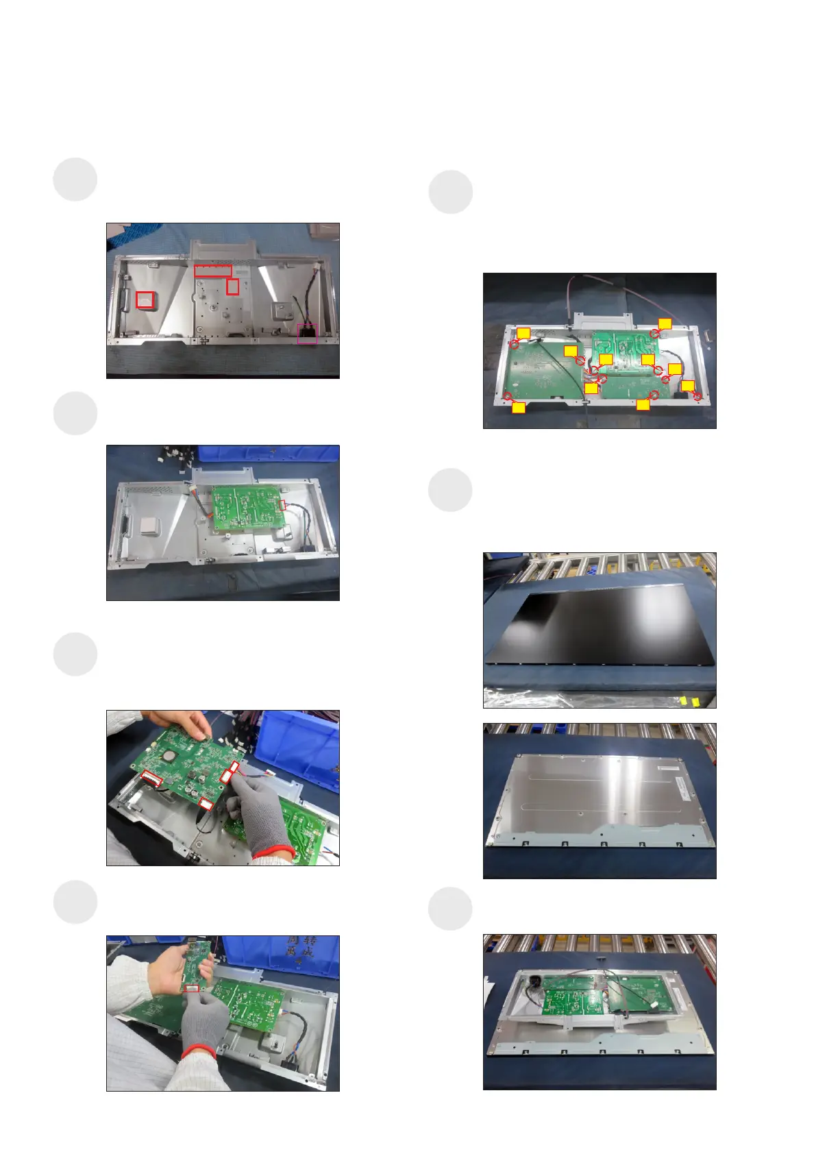
Panel preparation: Take out 1pcs panel module from
the carton, remove the protective film by tearing off
the tapes, then examine the panel surface
to place the screen faced down for later assembling.
according to inspection criteria. Turn over the panel
Move and put the bracket chassis module on the
back of the panel module.
9
1
5
10
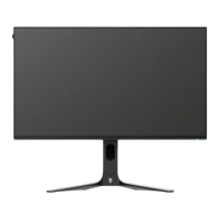
Use a Philips-head screwdriver to tighten 10pcs
screws for locking the power board, interface board
and main USB board with the bracket, then locate
the EDP cable and panel lamp cable into the hooks
of the bracket chassis module.
(No.1 screw size=M4x8, Torque=6±0.5kgfxcm;
No.2~10 screw size=M3x7.5, Torque=6±0.5kgfxcm)
Take 1pcs main USB board, then connect USB
connective cable to the connector of the main USB
board, then locate the board into the bracket.
S4
6
7
4
2
3
8
S6