EasyManuals Logo

Alienware M14X User Manual

Alienware M14X
122 pages
To Next Page IconTo Next Page
To Previous Page IconTo Previous Page
Page #79 background imageLoading...
Page #79 background image
CHAPTER 4: INSTALLING AND REPLACING COMPONENTS
77
5
4
3
2
1
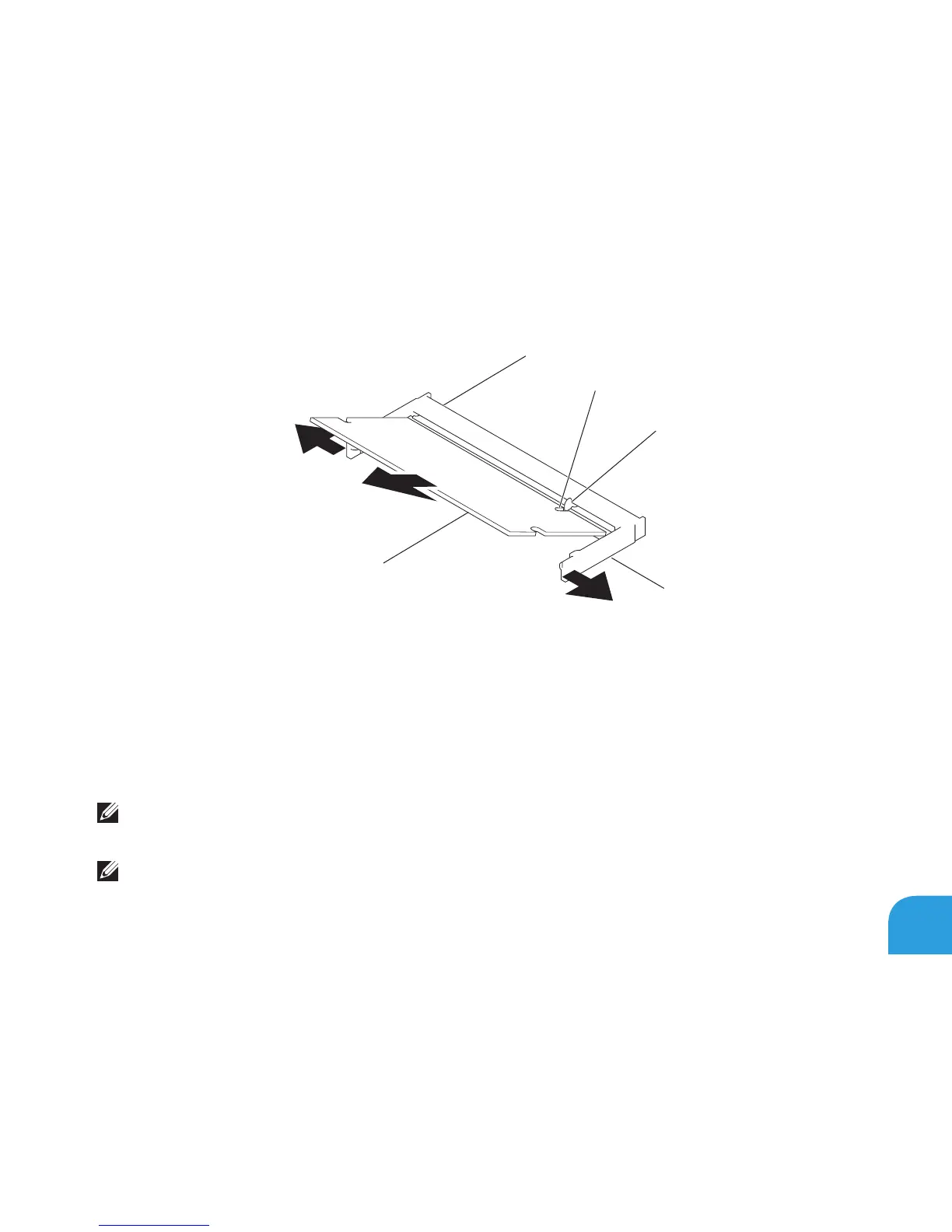
1 memory module 4 notch
2 spring locks (2) 5 memory module connector
3 tab
To replace the memory modules, perform the removal steps in reverse order. While inserting
the memory module into the connector align the notch on the memory module with the tab
on the memory module connector.
NOTE: If you need to install memory modules in two connectors, install a memory module
in the lower connector before you install a memory module in the upper connector.
NOTE: If the memory module is not installed properly, the computer may not boot.

Table of Contents

Other manuals for Alienware M14X

Questions and Answers:

Question and Answer IconNeed help?

Do you have a question about the Alienware M14X and is the answer not in the manual?

Alienware M14X Specifications

General IconGeneral
StorageUp to 750GB HDD or 256GB SSD
Weight6.45 lbs (2.93 kg)
Display14.0 inch (1600 x 900) WLED
RAMUp to 8GB DDR3
Operating SystemWindows 7 Home Premium
Battery8-cell Lithium Ion
Dimensions1.49 (inches)

Related product manuals