NOTE: The system board can be removed and installed along with the memory, ethernet and audio board, USB board, and
fan and heat sink-assembly. This simplifies the removal and installation procedure and avoids breaking the thermal bond
between the system board and heat sink.
About this task
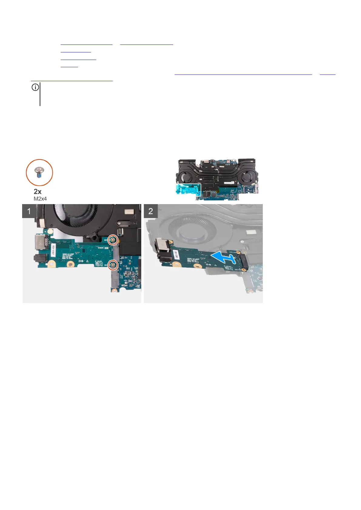
The following image(s) indicate the location of the power button and provides a visual representation of the removal procedure.
Steps
1. Remove the three screws (M2x2) that secure the power-button bracket to the palm-rest and keyboard assembly.
2. Lift the power-button bracket off the power button.
3. Lift the power button, along with its cable, off the palm-rest and keyboard assembly.
Installing the power button
Prerequisites
If you are replacing a component, remove the existing component before performing the installation process.
About this task
The following image(s) indicate the location of the power button and provides a visual representation of the installation procedure.
62