6. Remove the fans.
7. Remove the rear I/O-cover.
8. Remove the solid-state drive bracket.
About this task
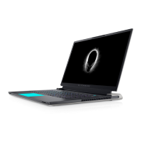
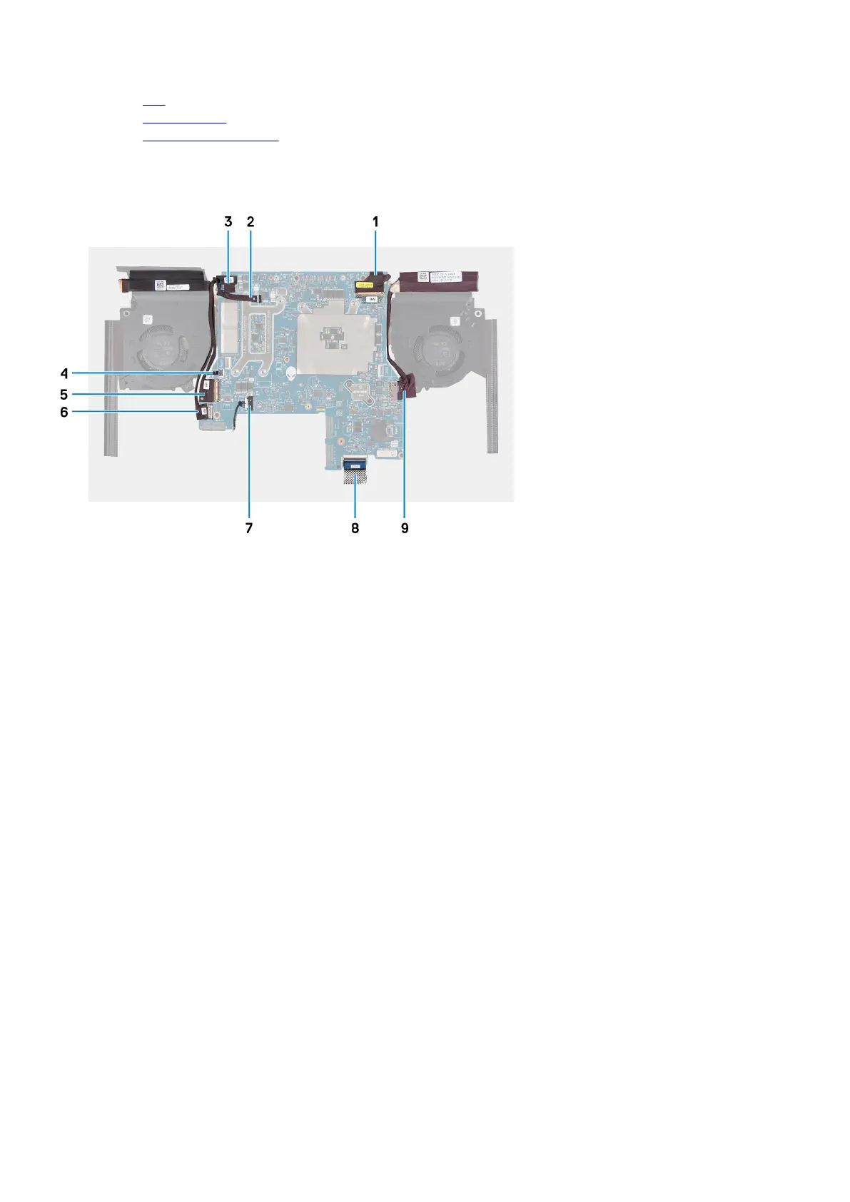
The following image indicates the connectors on your system board.
1. Display cable 2. Alien head LED cable
3. Camera cable 4. Power-button cable
5. I/O-board cable 6. Headset port cable
7. Speaker cable 8. Keyboard-controller board cable
9. Power-adapter port cable
The following image(s) indicate the location of the system board and provides a visual representation of the removal procedure.
47