EasyManua.ls Logo

Align Trex SE User Manual

Align Trex SE
13 pages
To Next Page IconTo Next Page
Page #1 background imageLoading...
Page #1 background image
Align Trex Se Setup Guide
Align Trex SE Setup Guide. version 1.0
Although I have successfully flown nitro and electric helis in the past I only recently discovered that my setups were
never actually correct. The difference in performance of a correctly configured heli and what I thought was correct is
really amazing. This is not a complete build but information on how to correctly setup your servos, linkage, pitch and
throttle curve so you have a smooth operating heli.
The following steps are based on a Trex SE that has been correctly assembled and all components installed. The
radio used is the Spektrum DX6. These steps are specific to the Spektrum DX6 so please see your manufacturers
instructions for placing your radio into the correct helicopter mode, in this case CCPM, and other options such as
servo reversing, gyro gain, etc. Radio settings, rates, degrees and any measurements shown in this guide are from
my working SE. Do not assume that by using the same values you will get the same results. Please verify all your
settings and general operation of your heli. I will always try to keep this information updated and error free however it
is your responsibility to make sure your heli is operating correctly.
#1 Radio Setup (Spektrum DX6)
The battery to your helicopter does not need to be connected at this time.
First we will set the radio into Heli Mode.
While pressing up on the scroll and increase buttons, turn the power switch on. You are now in
http://www.digimemphoto.com/pdf/ (1 of 13)1/25/2006 7:09:05 PM
Question and Answer IconNeed help?

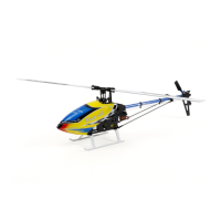
Do you have a question about the Align Trex SE and is the answer not in the manual?

Align Trex SE Specifications

General IconGeneral
BrandAlign
ModelTrex SE
CategoryToy
LanguageEnglish

Summary

Radio Setup (Spektrum DX6)

System Mode Configuration

Configures radio system modes like TYP, HE, and A for proper helicopter operation.

Function Mode Operations

Accesses and sets radio functions, including servo reversing and trims for control.

CCPM Mixing Parameters

Sets CCPM mixing for swashplate control, defining cyclic and collective pitch angles.

Servo Mounting, Connections, Direction, and Centering

Servo Mounting and Connections

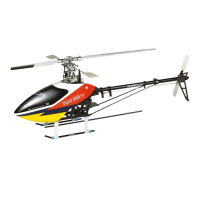
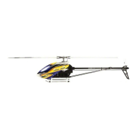
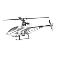
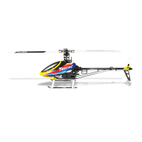
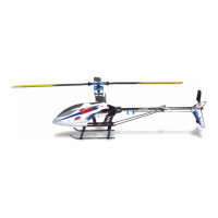
Details physical mounting and electrical connections for helicopter servos on the frame.

Servo Direction Verification

Checks and corrects servo movement direction for all control surfaces based on stick input.

Subtrim for Servo Centering

Utilizes subtrim to fine-tune servo arm alignment for precise centering of control surfaces.

Linkage Adjustment, Control Alignment, and Pitch

Head Linkage Alignment

Adjusts head linkages to ensure proper swashplate and blade alignment for correct control.

Zero Pitch Setting Procedure

Sets the main rotor blades to zero pitch using a pitch gauge for accurate measurement.

Positive Collective Pitch Adjustment

Adjusts the collective stick input to achieve the correct positive pitch range for the blades.

Negative Collective Pitch Adjustment

Adjusts the collective stick input to achieve the correct negative pitch range for the blades.

Setting up the Tail Rotor, Tail Rotor Servo, and Gyro

Tail Servo Placement and Linkage

Mounts and connects the tail rotor servo, aligning linkage for zero pitch.

Gyro Direction Confirmation

Confirms the correct operational direction of the tail rotor gyro system.

Tail Rotor Servo Travel Limit

Sets the maximum travel limits for the tail rotor servo to prevent binding or over-travel.

Verify Throttle Operation

Throttle and Motor Operation Verification

Verifies correct ESC connection, motor rotation, and rotor spin direction.

Final Check

Control Surface Binding Check

Checks all control surfaces for smooth movement without binding or rubbing.

Servo Arm-to-Component Clearance

Ensures servo arms have adequate clearance from other components during full movement.

Main Gear Mesh Calibration

Adjusts the play between the motor pinion and main gear for optimal meshing and durability.

Switch Functions and Notes

Flight Mode Switch Settings

Defines the pitch and throttle curves associated with each flight mode switch position.

Throttle Hold Switch Operation

Describes the function and purpose of the throttle hold switch for safety.

Aileron D/R Switch Role

Explains the function of the Aileron Dual Rate switch for gyro head hold control.

Elevator D/R Switch Default

Details the factory default settings for the Elevator Dual Rate switch.

Related product manuals