EasyManua.ls Logo

Alinco DR-135TMkIII - User Manual

Alinco DR-135TMkIII
55 pages
Print Icon
To Next Page IconTo Next Page
Loading...
Rhein Tech Laboratories, Inc. Client: Alinco, Inc.
360 Herndon Parkway Model: DR-235TMkIII
Suite 1400 Standards: FCC 15.121
Herndon, VA 20170 & IC RSS-215
http://www.rheintech.com
Report: 2006179
Page 23 of 41
Appendix J: Manual
Please see the following pages.

Table of Contents

Questions and Answers

  • G
    grobertsAug 15, 2025
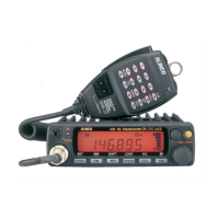
    Why Alinco Transceiver does not transmit and cannot be reset?
    • K
      Katelyn HaleyAug 15, 2025
      If your Alinco Transceiver won't transmit and can't be reset, it could be because the DSUB-9 port has been connected to a PC without installing the EJ-41U. Disconnect the cable and install EJ-41U properly.
  • T
    Theresa HarrisAug 19, 2025
    Why is there no sound coming from the Alinco Transceiver speaker?
    • M
      Michael RogersAug 19, 2025
      If no sound is coming from the Alinco Transceiver's speaker, there might be a couple of reasons: * The squelch might be muted. Try decreasing the squelch level. * Tone or DCS squelch might be active. In this case, turn off CTCSS or DCS squelch.
  • S
    Sean RussoAug 21, 2025
    What to do if PTT key is pressed but transmission does not occur on Alinco DR-135TMkIII Transceiver?
    • J
      Jennifer WilliamsAug 22, 2025
      If you press the PTT key on your Alinco Transceiver and transmission doesn't occur, check these potential causes: * Ensure the microphone connection is properly connected. * Verify the antenna connection is properly connected.
  • A
    Alicia PhillipsAug 25, 2025
    Why Alinco DR-135TMkIII Transceiver does not work in the APRS mode?
    • K
      Kevin PowellAug 26, 2025
      If your Alinco Transceiver isn't working in APRS mode, consider the following: * Ensure the connections and parameters are configured properly. * Use PC to configure the TNC, if the unit is not configured for automatic transmission. * Adjust squelch level properly, if the squelch is open. * Wait until GPS receiver receives data from satellites, if GPS receiver is not receiving the data from the satellites.
  • T
    tyroneedwardsAug 28, 2025
    Why Alinco DR-135TMkIII Transceiver does not work in the packet mode?
    • H
      hardinchristianAug 28, 2025
      If your Alinco Transceiver isn't working in packet mode, here are some things to check: * Make sure the connections and configurations are properly set for EJ-41U/TNC. * Follow the instruction, configure and retry, if the unit is not in the data mode. * Adjust squelch level properly, if the squelch is open. * Use command to configure the speed, if the data transmission speed is not configured. * Use straight RS-232C cable, if the cable is not straight type.
  • J
    Jennifer CarlsonSep 1, 2025
    How to unlock the Alinco DR-135TMkIII Transceiver if key and dial do not function?
    • M
      Mark McleanSep 1, 2025
      If the key and dial on your Alinco Transceiver aren't working, it's possible that the key-lock function is activated. Try canceling the Key-lock function.
  • C
    Caitlin SmithSep 4, 2025
    What to do if rotating dial will not change memory channel on Alinco DR-135TMkIII?
    • M
      Mr. Kevin PorterSep 4, 2025
      If the rotating dial on your Alinco Transceiver won't change the memory channel, the transceiver might be in CALL mode. Press the VFO or memory mode.
  • S
    Scott SimmonsSep 7, 2025
    What to do if Alinco DR-135TMkIII fuse is blown?
    • G
      gibsonjohnSep 7, 2025
      If the fuse is blown, check and solve the problem that resulted in the blown fuse. Replace the fuse with a new one.
  • D
    Darius WallaceSep 12, 2025
    What to do if power is on but nothing appears on Alinco DR-135TMkIII display?
    • K
      Kathleen ThomasSep 12, 2025
      If the power is on but nothing appears on the Alinco Transceiver's display, the + and - polarities of the power connection might be reversed. Connect the red lead to the plus terminal and the black lead to the minus terminal of the DC power supply.

Summary

Appendix J: Manual

Warning

Environment and condition of use

Safety guidelines for operating environment and conditions.

Handling this product

Precautions for safe handling and operation of the device.

About power-supply

Guidelines for proper power supply connection and usage.

In case of emergency

Procedures to follow in emergency situations concerning the product.

About transceiver

General advice and precautions for using the transceiver.

About power-supply

Specific advice on power supply connection and usage, including European standards.

CAUTION

Environment and condition of use

Environmental and usage restrictions to prevent damage or hazards.

Before operating the transceiver

Attention

Important points to note before operating the transceiver.

Notice to California resident users

Special notice for California users regarding product materials.

Introduction

1. New and Innovative Features

2. Standard Accessories

3. Initial Installation

For a base station set up

Step-by-step guide for setting up the transceiver as a base station.

For a mobile station set up

Instructions for installing the transceiver in a vehicle.

RF Hazard Warning

Critical safety warning regarding radio frequency exposure during operation.

3. Initial Installation

External power supply control & power lamp functions

Explanation of external power supply connection and power lamp operation.

Power supply voltage display function

How to display and check the transceiver's power supply voltage.

4. Part Names and Functions

Front Panel

Identification and function of controls on the front panel of the transceiver.

Rear Panel

Identification and function of connectors and controls on the rear panel.

Display

Explanation of the transceiver's LCD display icons and their meanings.

Microphone

Details of the microphone controls and connector pinout.

5. Basic Operations

Turning the unit on and off

Step-by-step instructions for powering the transceiver on and off.

Audio Volume level setting

How to adjust the audio output volume level.

Squelch level setting

Adjusting the squelch to control background noise and signal reception.

VFO mode

Explanation of the Variable Frequency Oscillator mode for frequency selection.

Changing the channel step

How to select the frequency step size for tuning and scanning.

CTCSS; DCS setting

Setting CTCSS tones and DCS codes for selective calling and squelch.

Memory Mode

Managing memory channels for storing and recalling frequencies and settings.

CALL mode

Using the CALL mode for quick recall of a specific memory channel.

To receive signals

Procedures for receiving signals and monitoring activity.

To transmit

Steps for transmitting signals, including power level selection.

REPEATER (DUPLEX) Operation

Shift Direction and Offset frequency setting

Configuring repeater offset and shift direction for duplex operation.

6. Parameter Setting Mode

To use the Parameter Setting mode

Guide on how to enter and navigate the parameter setting menu.

Channel Step setting

Configuring the frequency step size for VFO operation.

Scan Type

Selecting the condition for resuming scan operations.

Beep Sound

Enabling or disabling audible beeps for key presses and settings.

Time-Out-Timer

Setting a limit for continuous transmission to prevent repeater lockout.

TOT Penalty

Configuring a penalty time after TOT expiration to prevent immediate re-transmission.

APO-Auto Power OFF

Enabling automatic power off feature to save battery.

Tone-Burst Frequency

Setting the audible tone frequency for activating repeaters.

Busy-Channel-Lock-Out

Preventing transmission when a channel is busy.

Theft Alarm

Setting up an alarm to deter improper removal of the unit.

Alphanumeric Tag

Assigning text tags to memory channels for easier identification.

Dimmer

Adjusting the display brightness for better visibility.

7. Advanced Operations

SCANNING FUNCTION

Utilizing the transceiver's automatic signal search capabilities.

Program Scan

Scanning within a user-defined frequency range.

Tone Scan

Searching for CTCSS tones on incoming signals.

DCS scan

Searching for DCS codes on incoming signals.

KEY-LOCK FUNCTION

Locking keys to prevent accidental changes.

TONE BURST

Transmitting a tone burst for repeater activation.

Digital voice communication

Enabling digital voice communication via an optional unit.

WIDE; NARROW (Reduction of the Mic. Gain; Deviation)

Switching between wide and narrow modes for transmission and reception.

AUTO-DIALER

Transmitting pre-programmed DTMF tones for remote control.

THEFT ALARM (Optional ADALM135 required for FXE models)

Setting up an alarm to deter improper removal of the unit.

AM Mode Reception (DR235 TMkII only)

Switching to AM reception mode for specific frequency bands.

7. Advanced Operations

CABLE CLONE

Copying programmed data and settings between units.

8. PACKET OPERATION

[To operate packet using EJ-41 U]

Connecting and operating packet mode using the EJ-41U unit.

Packet Mode Setting

Configuring settings for packet mode operation.

[To operate packet using an external TNC]

Connecting and operating packet mode with an external TNC.

[To operate APRS]

Operating Automatic Packet Reporting System (APRS).

[SET UP]

Setting up the transceiver and GPS receiver for APRS operation.

[APRS Operation]

Performing APRS operations using the transceiver and PC.

9. Remote Control Operation

Remote Command and Frequency Entry

Entering commands or frequencies for remote control operation.

Locking Remote Control Input

Preventing remote control inputs by activating the lock function.

[Entering a frequency directly]

Inputting frequencies directly using the microphone's numerical keys.

[Entry method depending on tuning step]

Understanding how tuning step affects direct frequency entry.

10. Maintenance; Reference

Reset

Procedure for resetting the transceiver to factory default settings.

Trouble Shooting

Common problems and their potential causes and solutions.

11. Optional accessories

12. Specifications

Appendix

TNC Commands List

List of commands supported by the built-in TNC for packet operations.

Alinco DR-135TMkIII Specifications

General IconGeneral
ModeFM
Voltage13.8V DC ±15%
Antenna Impedance50 ohms
Adjacent Channel Selectivity70 dB
Frequency Range144-148 MHz
Current Consumption (RX)0.5A
Weight1 kg
ModulationF3E
Sensitivity0.25 μV
Audio Output2W (at 10% distortion)

Related product manuals