GENERAL PUMP MAINTENANCE
07-23-03 Z08-00063B
ECN-02981
checking for binding or damage. Discard and
replace damaged items.
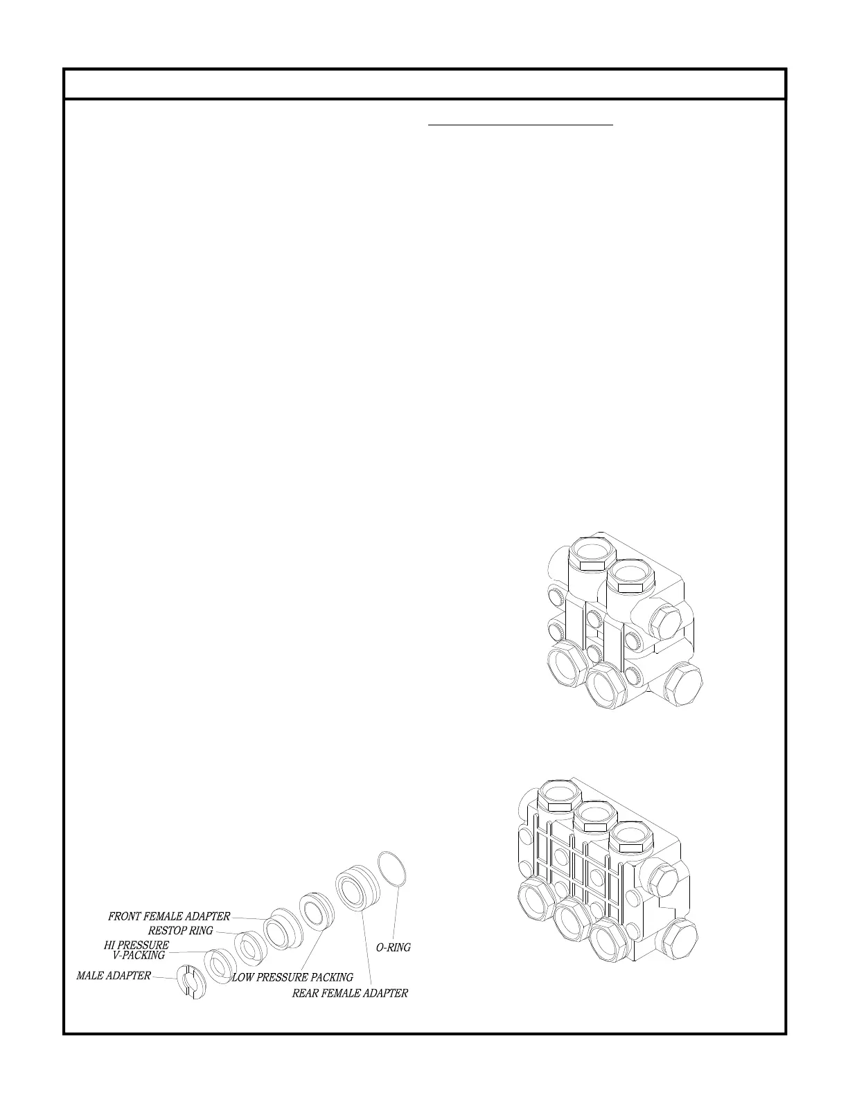
6. Lubricate packing cavities in the head and all
packings and adapters with pump crankcase oil.
7. Lay head on the bench with packing cavities up.
Install one male adapter in each cavity with the
flat side down.
8. Install one v-packing into each cavity with the
lips pointing down. A packing insertion too of
the appropriate size is recommended for this
operation.
9. Install the restop ring with the lips pointing
down.
10. Install a front female adapter into each cavity
with the flat side up. Make certain the adapter
goes all way down into the cavity.
11. Install the low pressure packing with the flat
side down.
12. Install the rear female adapter into each cavity
with the lips pointing down.
13. Lubricate o-rings with pump crankcase oil and
install one into the groove of each adapter.
14. Install one adapter and o-ring into each cavity
with the flat side up. Each adapter and o-ring
assembly should push into the head to
approximately 1/16 inch of being flush with the
surface of the head. Only hand pressure should
be required to perform this operation. This step
is VERY IMPORTANT. If the rear female adapter
does not fit almost flush, something is not
properly positioned. If a proper fit is obtained,
proceed to step 16. If a proper fit is not obtained,
remove the female adapters from the offending
cavity and reinstall items per steps 8 through
15.
15. Install head per “HEAD INSTALLATION”.
HEAD INSTALLATION
1. Prepare pump head per instructions in
“PACKING SERVICE”.
2. Rotate the plungers so the outer plungers are
projecting the same distance from the crankcase.
3. Lubricate the exposed plungers with crankcase
oil.
4. Start the head onto the plungers and using a
soft mallet, tap the head evenly until it comes in
contact with the crankcase.
5. Start the cap screws through the head and into
the crankcase. Do not forget the lock washer on
each screw.
6. Tighten all cap screws by hand.
7. Torque the cap screws to the value indicated in
the “TORQUE” section of PUMP
SPECIFICATIONS. Torque the cap screws in the
order listed below.
7
8
2
4
6
7
1
3
5
1
3
6
2
7
6
 Loading...