26 ML5000 Service Manual
4) Carefully remove the Fader Slave PCB from the Mono Fader PCBs by pulling it upwards
from the fader boards.
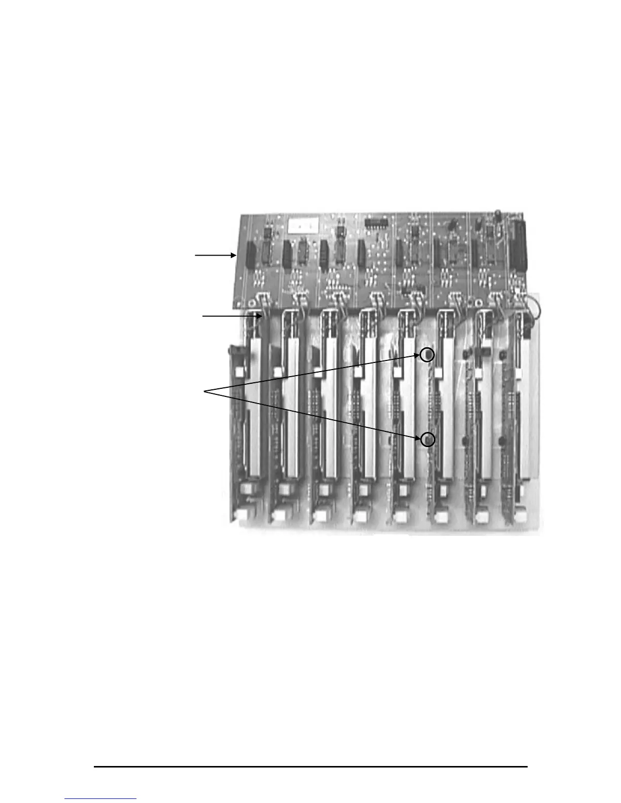
5) Once removed, turn the Fader Slave PCB over (see fig.3)
To remove a Mono Fader PCB, use a 5.5mm spanner to remove the relevant M3x4 Taptite Hex
Headed Screws (E) that attach the Mono Fader PCBs to the Input Fader Bracket (see fig.3).
To remove a fader remove the two relevant M3x5 Countersunk Pozi Screws with under-head pips (C)
as shown in fig.1. Then unplug the fader wireform from the Fader Slave PCB, the fader can now be
removed. De-solder the three fader wireform wires from the fader, taking note of the wire positions for
refitting.
Note: A fader can be removed without removing the IDC wireforms and Slave PCB.
To refit any of the PCB/Fader assemblies, follow the above procedure in reverse order. Ensure all
connectors and harnesses are correctly aligned and plugged on. Test for correct operation.
fig.3
Fader Slave PCB
Fader Wireform
E
 Loading...