Allen & Heath 14 XB-14 User Guide
INSERT
M1
LINE
MIC
100Hz
-6-10 63 26
GAIN
MIC
0
LINE
10
0
10
20
30
40
50
M1
MONO INPUT CHANNEL
1
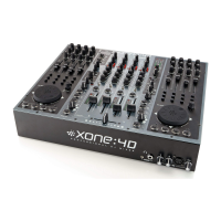
Mic Input Socket
Standard 3-Pin XLR socket wired as Pin 1=Chassis, Pin 2=hot
(+), Pin 3=Cold (-).
2
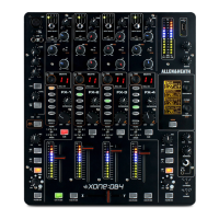
Line Input Jack Socket
Standard 1/4” (6.25mm) Jack socket for balanced or unbalanced line
level signals. Wired Tip=Hot (+), Ring=cold (-), Sleeve=Chassis.
The Line input overrides the Mic input, so if you want to hear
something plugged in to the xlr socket, make sure nothing is
plugged into the Line input.
3
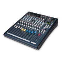
Insert Jack Socket
Standard 1/4” (6.25mm) Jack socket for unbalanced insert send and
return signals. Wired Tip=send, Ring=return, Sleeve=Chassis.
Nominal level is 0dBu. The insert point is after the 100Hz filter and
before the EQ.
4
Gain Control
This adjusts the gain of the input amplifier to match the signal level
of the input. The gain is varied from –6dB (attenuation) to +63dB
for signals plugged in to the xlr socket (Mic Input) and –10dB to
+26dB for signals plugged into the Line input jack.
5
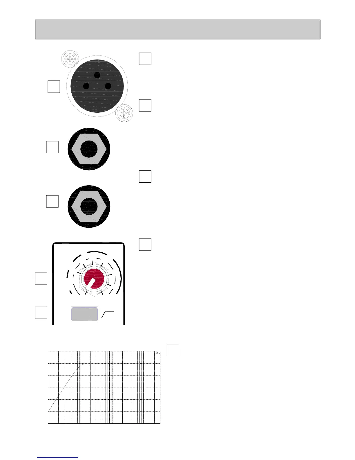
100Hz High Pass Filter
The Hi-pass filter is used for reducing pop noise and rum-
ble from microphone signals. It is a 2-pole (12dB per oc-
tave) filter with a corner frequency set at 100Hz.
The filter affects signals from both Mic XLR and Line jack
socket.
10.00 Hz 100.00 1000.00 10000.00 30000.00
-50.00
-40.00
-30.00
-20.00
-10.00
0.00
10.00
dBr
1
2
3
4
5
 Loading...