EasyManua.ls Logo

ALLEN & HEATH XONE 92 Service Manual

ALLEN & HEATH XONE 92
54 pages
To Next Page IconTo Next Page
Page #1 background imageLoading...
Page #1 background image
SERVICE MANUAL
Publication AP5296

Other manuals for ALLEN & HEATH XONE 92

Question and Answer IconNeed help?

Do you have a question about the ALLEN & HEATH XONE 92 and is the answer not in the manual?

ALLEN & HEATH XONE 92 Specifications

General IconGeneral
TypeAnalog
LFONo
Record OutputRCA
Filters2 VCF filters
Inputs4 phono, 4 line, 2 mic
OutputsMaster, Booth, Record, Headphone
Aux Sends2 aux sends
Mic Inputs2
Master OutputXLR
Booth Output1/4" Jack
Headphone Output1/4" Jack and 3.5mm Jack
MIDIMIDI out
CrossfaderVCA crossfader
EffectsNo built-in effects
Power SupplyInternal
Dimensions320mm x 358mm x 88mm

Summary

Servicing Precautions

Personnel and Facility Requirements

Requirements for qualified personnel and workspace.

Safety Procedures

Guidelines for mains power, cord, fuse, opening, closing, testing, shipping.

Servicing Notes – XONE:92

Technical Aspects and Fault Finding

Technology overview and methods for fault diagnosis.

Removing the Top Panel Assembly

Chassis and PCB Assembly Layout

XONE:92 Chassis Assembly View

Diagram showing the front view of the chassis assembly.

XONE:92 Front Panel Assembly View

Diagram showing the front panel assembly.

Component Identification

Front Panel Controls

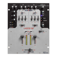
Identification of pots, switches, and LEDs on the front panel.

Rear Panel Connectors

Identification of I/O connectors on the rear panel.

XONE:92 Block Diagram

Mic/Stereo Return Schematic (003-136)

Stereo Channel Schematic (003-137)

Stereo Channel Schematic (Sheet 2)

Stereo Channel Schematic (Sheet 3)

Filter/MIDI PCB Schematic (003-138/003-143)

Filter/MIDI PCB Schematic (Sheet 2)

Filter/MIDI PCB Schematic (Sheet 3)

Filter/MIDI PCB Schematic (AG5300 Issue 3)

Filter/MIDI PCB Schematic (AG5300 Issue 3, Sheet 2)

Filter/MIDI PCB Schematic (AG5300 Issue 3, Sheet 3)

Master PCB Schematic (003-139)

Master PCB Schematic (Sheet 2)

Crossfader PCB Schematic (003-140)

Slave Card Schematic (003-141)

Slave Card Schematic (Sheet 2)

Power Supply Schematic (003-233)

ECN 984: Filter 1 & 2 PCB Modification

ECN 993: Filter Value Change and Diode Addition

ECN 1018: Master PCB Output Level Change

Rear Panel Connections

Input/Output Connectors

Identification of various input/output connectors on the rear panel.

Related product manuals