EasyManuals Logo

ALLEN & HEATH XB-14 User Manual

ALLEN & HEATH XB-14
40 pages
To Next Page IconTo Next Page
To Previous Page IconTo Previous Page
Page #21 background imageLoading...
Page #21 background image
Allen & Heath 21 XB-14 User Guide
8
9
10
7
9
10
LR
BAL
=
SIGNAL
PFL
PEAK
OO +6
PRE
PGM
FDR
BUS
AUX
0
5
10
15
20
30
40
50
OO
MIX B
+START/CUE
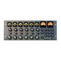
STEREO INPUT CHANNELS ST1 & ST2
FOR CLARITY ONLY ST1 CHANNEL IS DESCRIBED HERE
7
BAL
The balance control adjusts the relative levels of the left & right signals in
the stereo input channel as they are sent to the PGM bus and the MIX B
bus. Set to the mid position, the signals are balanced equally. With the
balance control set fully anticlockwise the right channel will be fully at-
tenuated and the left channel will increase by approximately 3.5dB.
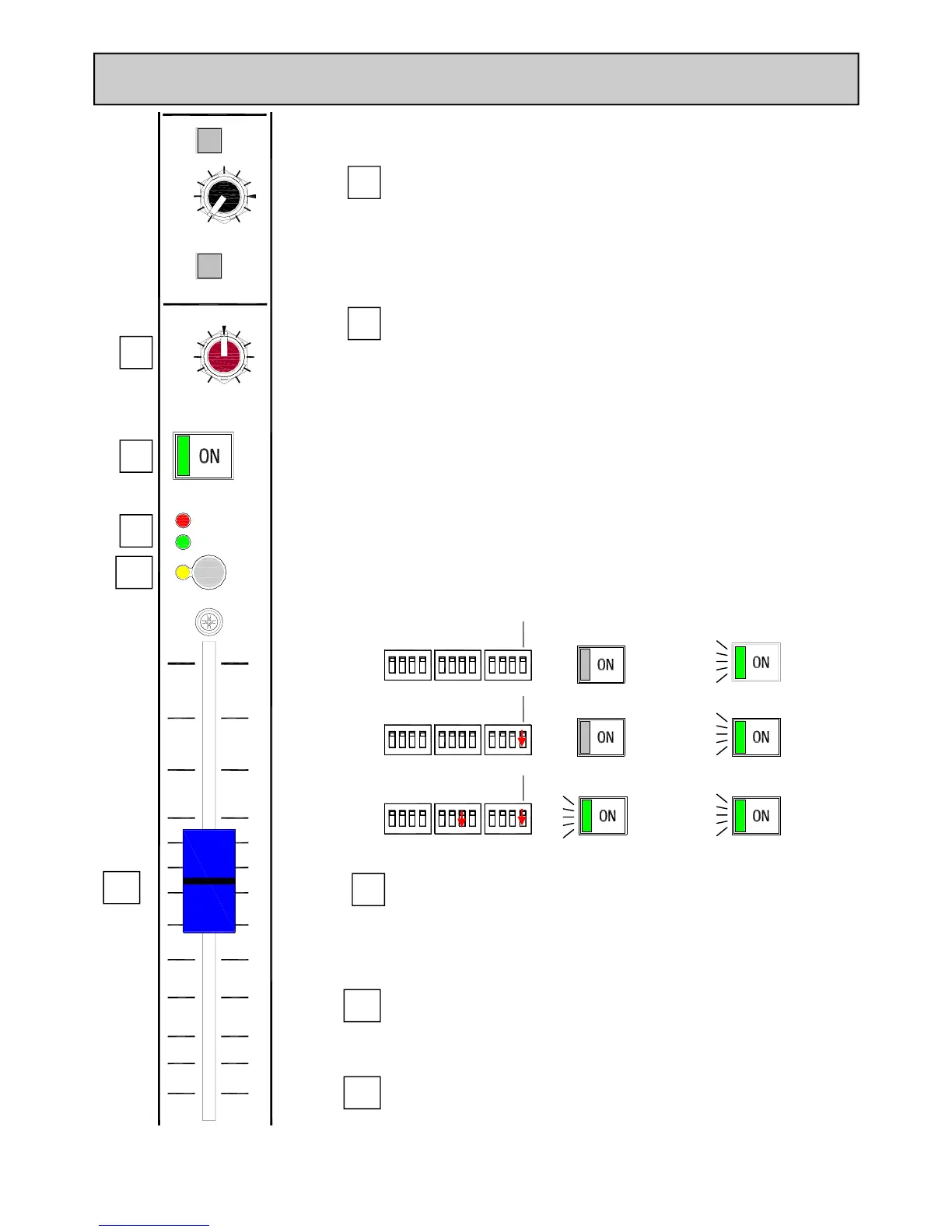
ON (+START/CUE) switch
The stereo channel ON switch operates the stereo channel mute cir-
cuitry, turning the signals to the PGM, MIX B and Aux buses on or off.
The switch is illuminated green when pressed.
The ON switch also activates the START/CUE logic signals (for the cor-
responding selected input) wired to the remote interface connector on
the rear panel.
There is an option to disable the mute circuit on all the stereo channels
(make the channels permanently ON) using the option switches on the
rear panel. This can be done for all 4 stereo channels together, retaining
the illumination switching (if the ON switch is being used for Start/Cue).
It can also be done on an individual channel basis by using the STEREO
INPUTS 1,2,3&4 slide switches in which case the illumination of the
switch will be jammed permanently ON.
8
SIGNAL & PEAK LEDs
The Signal LED illuminates when the pre-fader L or R signal level is above
–15dB.
The Peak LED illuminates and stays on for around 0.5 seconds when a
peak level is detected (pre-fader signal) within 5dB of clipping.
PFL Switch
Sends the summed L & R stereo channel signals to the PFL bus.
Fader
The 100mm fader controls the level of the stereo channel L & R signals
to the PGM bus, MIX B bus and post fade Aux.
There is no fader start logic feature on the stereo channel faders.
11
11
ON ON ON ON ON ON ON ON ON ON ON ON
MONO INPUTS
1234 T1T212 34
STEREO INPUTS
)
ON Switch Not Pressed ON Switch Pressed
Channel Muted
ON ON ON ON ON ON ON ON ON ON ON ON
MONO INPUTS
1234 T1T212 34
STEREO INPUTS
)
Channel ON
Channel ON
Channel ON
Standard
Operation
STEREO
ON Switch
Optional
Modes
Mute
Disabled
(Always ON)
LEDs FOLLOW
SWITCH
(All stereos)
ON ON ON ON ON ON ON ON ON ON ON ON
MONO INPUTS
1234 T1T212 34
STEREO INPUTS
)
Channel ON Channel ON
Mute
Disabled
(Always ON
All Stereos)
LEDs always
illuminated
(On ST1 only)
CUE Deck START Deck
CUE Deck
START Deck
START Deck
CUE Deck

Other manuals for ALLEN & HEATH XB-14

Questions and Answers:

Question and Answer IconNeed help?

Do you have a question about the ALLEN & HEATH XB-14 and is the answer not in the manual?

ALLEN & HEATH XB-14 Specifications

Operating Levels IconOperating Levels
Mono channel Mic input range+6 to –63dBu
Mono channel Line input range+10 to –26dBu
Insert point nominal level0dBu
Stereo input nominal level0dBu
Telco channel input range+10 to –26dBu
External monitor inputs nominal level0dBu
Output Levels IconOutput Levels
PGM L & R outputs nominal level+4dBu
PGM Mono output nominal level0dBu
PGM L & R inserts nominal level-2dBu
Aux output nominal level0dBu
Mix B outputs nominal level0dBu
Rec outputs nominal level0dBu
Audio Performance IconAudio Performance
THD+n Mic in to PGM L/R Out0.003%
THD+n Mic in to PGM Out0.007%
THD+n Line in to PGM L/R out0.004%
THD+n Stereo in to PGM out0.003%
Noise Mic Pre EIN-127dBu
Noise PGM out-92dBu
Frequency Response IconFrequency Response
Mic in to PGM L/R Out20Hz to 20kHz
Line in to PGM L/R out10Hz to 30kHz
Stereo in to PGM L/R out10Hz to 30kHz
Headroom IconHeadroom
Analogue Headroom Outputs21dB
USB in & out headroom14dB
Analogue Headroom Mix point24dB
Crosstalk & Attenuation IconCrosstalk & Attenuation
Mono fader attenuation 1kHz/10kHz-99/-90
Mono ON switch attenuation 1kHz/10kHz-96/-80
TELCO fader attenuation 1kHz/10kHz-99/-92
TELCO ON switch attenuation 1kHz/10kHz-102/-100
Stereo fader attenuation 1kHz/10kHz-100/-91
Stereo ON switch attenuation 1kHz/10kHz-102/-102

Related product manuals