Programming
5-54
This group contains the parameters needed for an optional communications adapter to communicate with the
drive.
Adapter
I/O
[Data In A1 throu
h D2]
Parameter # 111 - 118
Parameter Type Read & Write
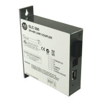
These parameters are used to write real time data values
from a source controller (PLC, SLC, etc.) to the drive. This
is accomplished by programming a parameter number into
the [Data In] parameters. The value programmed into the
source controller’s output image table will be written to the
drive parameter identified in the corresponding [Data In]
parameter.
Bulletin 1305 drive Controller Output Image Table (i.e. PLC, SLC, etc.)
Important: addressing information that defines which controller I/O
address corresponds to a [Data In] parameter is determined by the
dip switch settings on the external communication module. Refer to
the appropriate Bulletin 1203 Communication Module User Manual
for details.
Refer to Appendix B for additional information.
Parameter
111 Data In A1
112 Data In A2
113 Data In B1
114 Data In B2
115 Data In C1
116 Data In C2
117 Data In D1
118 Data In D2
Important: The drive parameter that is accessed indirectly using Data In will not be stored permanently and automatically to
EEPROM (due to the high potential update rate from a PLC). A manual operation is necessary for permanent storage. The HIM
EEPROM command, Save Values, or using parameter (64) [Set Defaults] will perform this task. Similarly, to restore the values to
the ones the drive had before Data In was configured, the HIM Recall Values Function can be used.
[Data Out A1 throu
h D2]
Parameter # 119 - 126
Parameter Type Read & Write
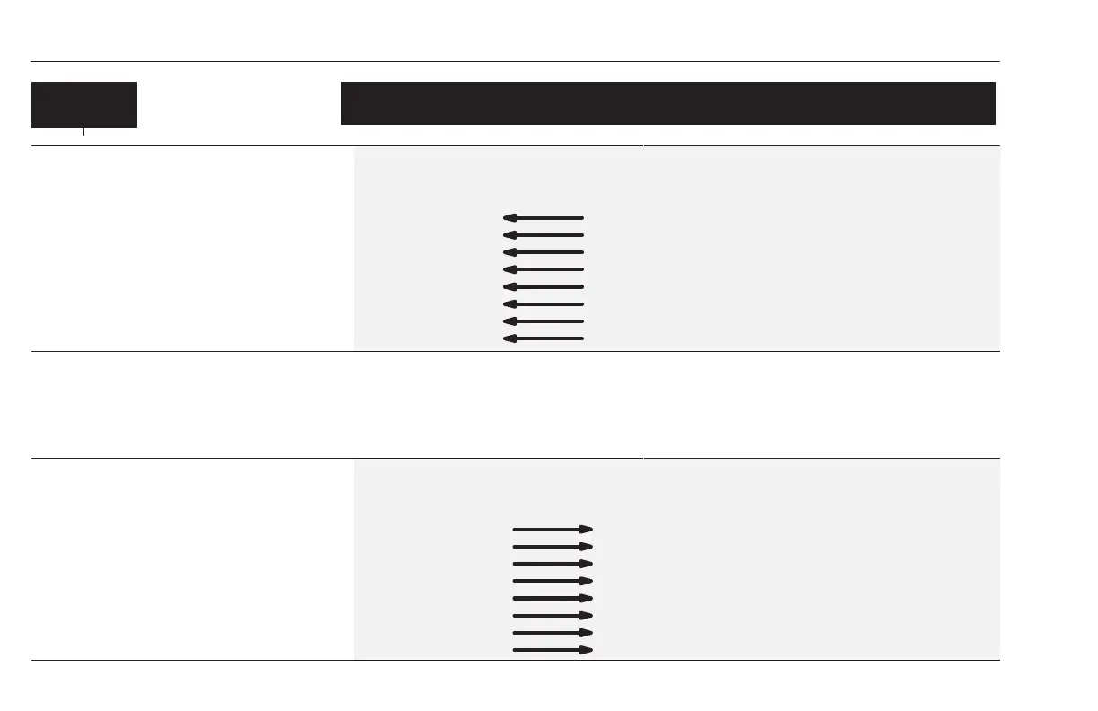
These parameters are used to write real time data values
from the drive to a destination controller. This is
accomplished by programming a parameter number into
the [Data Out] parameters. The real time value of that
parameter will be written to the input image table of the
destination controller.
Bulletin 1305 drive Controller Input Image Table (i.e. PLC, SLC, etc.)
Important: addressing information that defines which controller I/O
address corresponds to a [Data Out] parameter is determined by the
dip switch settings on the external communication module. Refer to
the appropriate Bulletin 1203 Communication Module User Manual
for details.
Refer to Appendix B for additional information.
119 Data Out A1
120 Data Out A2
121 Data Out B1
122 Data Out B2
123 Data Out C1
124 Data Out C2
125 Data Out D1
126 Data Out D2
Parameter
efesotomasyon.com - Allen Bradley,Rockwell,plc,servo,drive
 Loading...