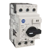
1
2
CLACK
150 mm
5.90"
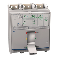
3
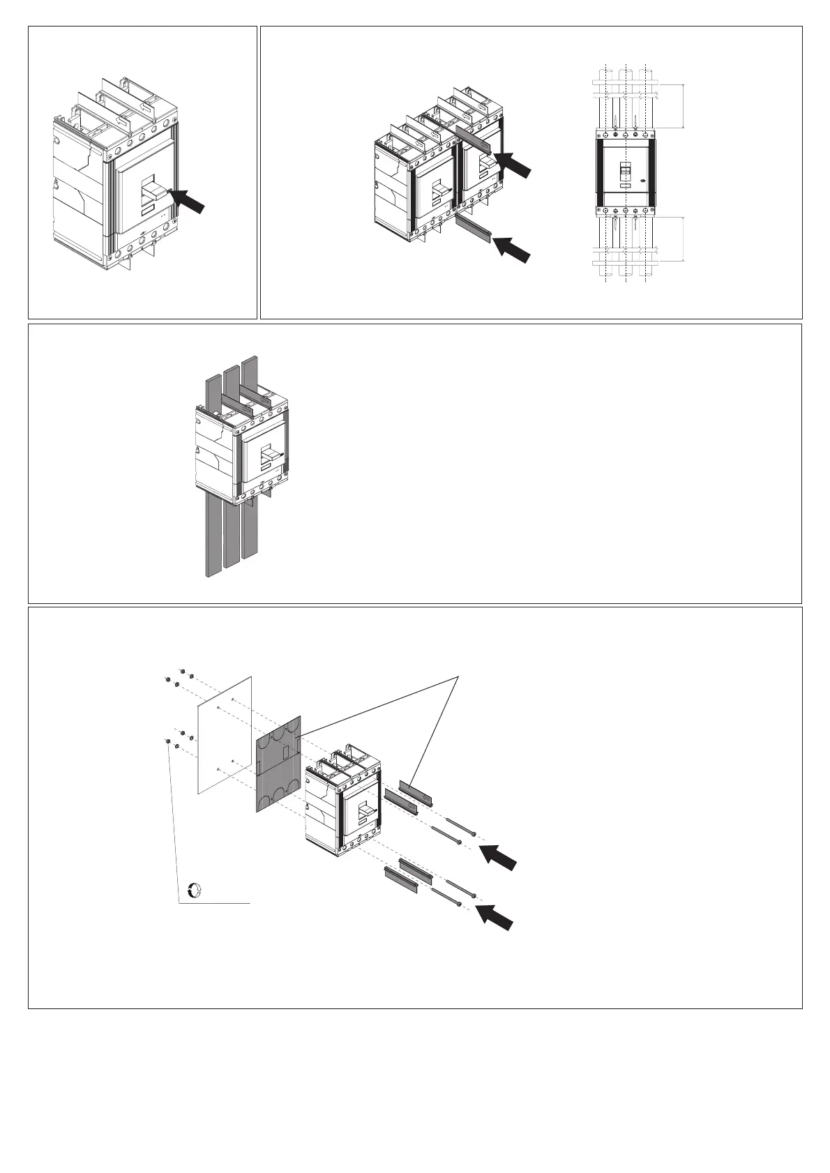
4
- Use cable or insulated busbars/ or perform specific type test on the
installation.
- Usare cavi o barre isolate/ o eseguire prove di tipo specifiche sull'
installazione.
- Kabel oder isolierte Sammelschienen verwenden / oder die spezifische
Typprüfung auf der Installation durchführen.
- Utiliser un câble ou des barres isolées/ ou réaliser un test de type spé -
cifique sur installation.
- Utilizar un cable o barras aisladas / o efectuar una prueba de tipo es
-
pecífico sobre instalacíon.
2 Nm
17 lb-in
(2)
Mandatory for UL application
Mandatory for IEC application
when Ue ≥ 500V
150 mm
5.90"
DIR 1000437R0002 Version 02
Maximum recommended conductor support distance

 Loading...