Rockwell Automation Publication 1606-RM055A-EN-P - December 2016 21
Basic Power Supply 5 A
Dielectric Strength
The output voltage is floating and has no ohmic connection to the ground.
Type and factory tests are conducted by the manufacturer. Field tests can be
conducted in the field using the appropriate test equipment, which applies the
voltage with a slow ramp (2 s up and 2 s down). Connect all input-terminals
together and all output poles before conducting the test. When testing, set the
cutoff current settings to the value in the following table.
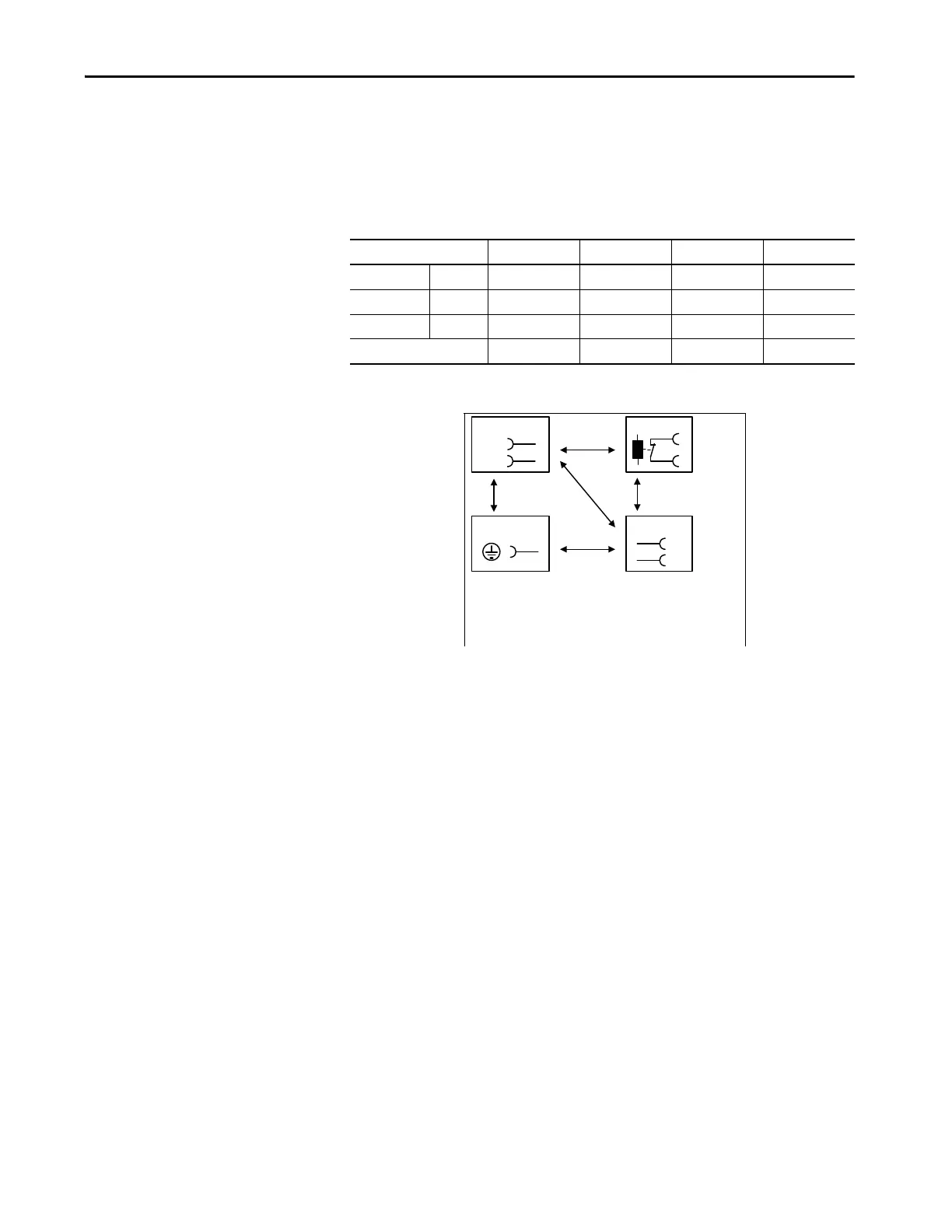
Figure 24 - Dielectric Strength
To meet the PELV requirements according to EN60204-1 § 6.4.1, we
recommend that either the + pole, the – pole or any other part of the output
circuit be connected to the protective earth system. This helps to avoid
situations in which a load starts unexpectedly or cannot be switched off when
unnoticed earth faults occur.
ABCD
Type test 60 s 2500V AC 3000V AC 1000V AC 500V AC
Factory test 5 s 2500V AC 2500V AC 500V AC 500V AC
Field test 5 s 2000V AC 2000V AC 500V AC 500V AC
Cutoff current setting > 10 mA > 10 mA > 15 mA > 1 mA
DA
C
B
B
*)
N
L
Input DC-ok
Earth, PE
Output
-
+
B*) When testing input to DC-OK ensure that
the max. voltage between DC-OK and the
output is not exceeded (column D). We
recommend connecting DC-OK pins and the
output pins together when performing the test.

 Loading...