Rockwell Automation Publication 1734-UM001E-EN-P - July 2013
30 Install POINT I/O Modules
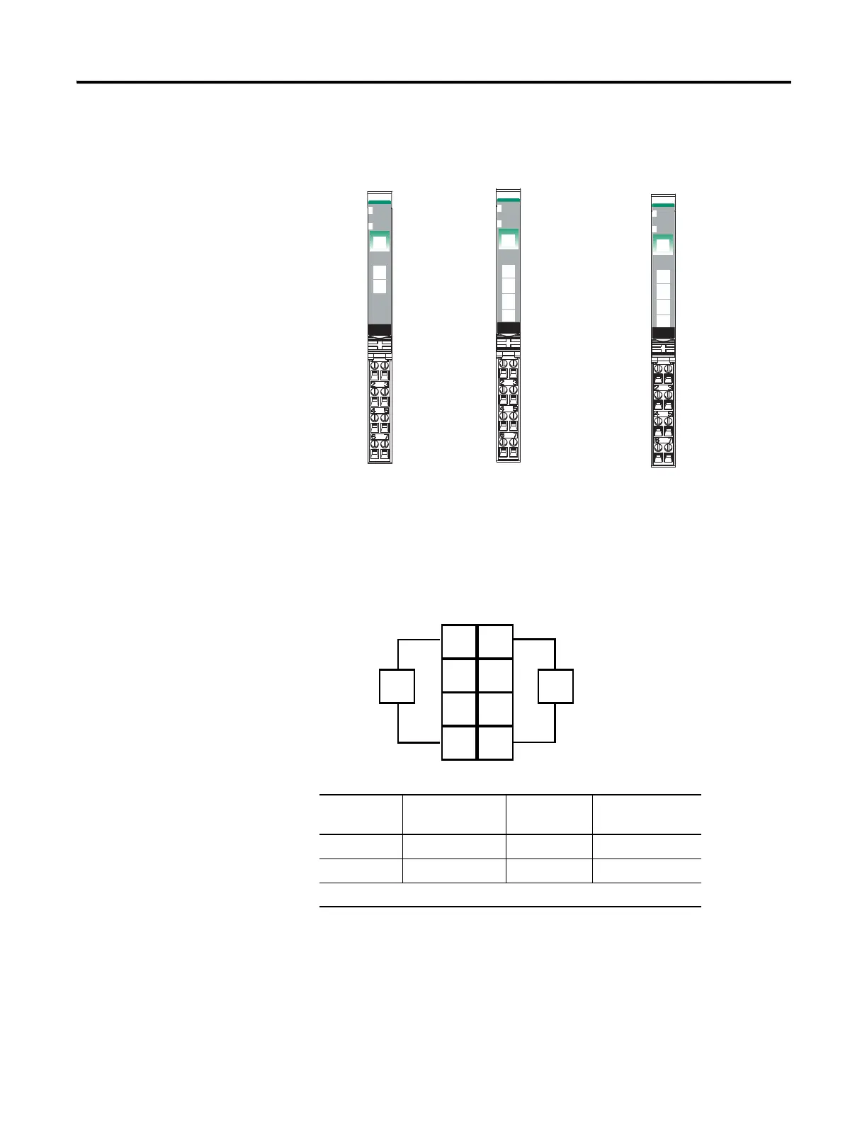
1734-OV2E, 1734-OV4E, and 1734-OV8E Sink Output Modules
DC Sink Output Module Cat. No. 1734-OV2E Wiring Diagram
Channel Output Terminal Power Common
Terminal
Channel 0 0 6 4
Channel 1 1 7 5
Module power is supplied from the internal power bus.
24VDC
Sink
Output
Module
Status
Network
Status
1734
OV2E
NODE:
0
1
24VDC
Sink
Output
Module
Status
Network
Status
1734
OV4E
NODE:
0
1
2
3
2
24VDC
Sink
Output
Module
Status
Network
Status
1734
OV8E
NODE:
0
1
2
3
4
5
6
7
Module Status
Network Status
Status of Output 1
Status of Output 0
Status of Output 0 & 4
Status of Output 1 & 5
Status of Output 2 & 6
Status of Output 3 & 7
Output 1
Output 1
Output 3
V
Output 1
Output 5
Output 3
Output 7
Output 4
Output 6
Output 2
Output 0
Output 0
Output 2
V
V
V
C
N/C
Output 0
C
N/C
V
V
46120
46121 46122
C = Common
V = Supply
1734-OV2E
1734-OV4E
1734-OV8E
Status of Output 0 & 4
Status of Output 1 & 5
Status of Output 2 & 6
Status of Output 3 & 7
Module Status
Network Status
Module Status
Network Status
Out 0
Out 1
NC
NC
C
C
V
V
Load
Load
V = 12/24V DC, C = Common
Field power is supplied from internal power bus
0
2
6
4
3
5
7
1
 Loading...


