Rockwell Automation Publication 1734-UM001E-EN-P - July 2013
120 Calibrate Your Analog Modules
Tools Required to Calibrate
Your Analog Modules
To maintain your module’s accuracy specifications, we recommend you use
calibration instruments with specific ranges. See the table for a list of the
recommended instruments for each module.
You must be online to calibrate your analog I/O modules. We recommend the
module not be actively controlling a process when you calibrate it.
Input calibration consists of the following steps for an example of 2 channels.
1. Connect the calibration system.
2. Allow the system to warmup for at least 10 minutes.
3. Connect current or voltage source to channel 0 by applying
4 mA (current) or 0V (voltage).
4. Begin calibration.
5. Select both channels.
6. Accept Low cal for channel 0 (both status indicators blink).
7. Set current or voltage source to high value (20 mA current; or +10V
voltage).
8. Accept High cal for channel 0 (channel 0 status indicator turns off if
calibration was good, but channel 1 status indicator still blinks).
9. Connect current or voltage source to channel 1.
10. With high cal now applied to channel 1, accept High cal for channel 1.
11. Set current or voltage source to Low value.
12. Accept Low cal for channel 1.
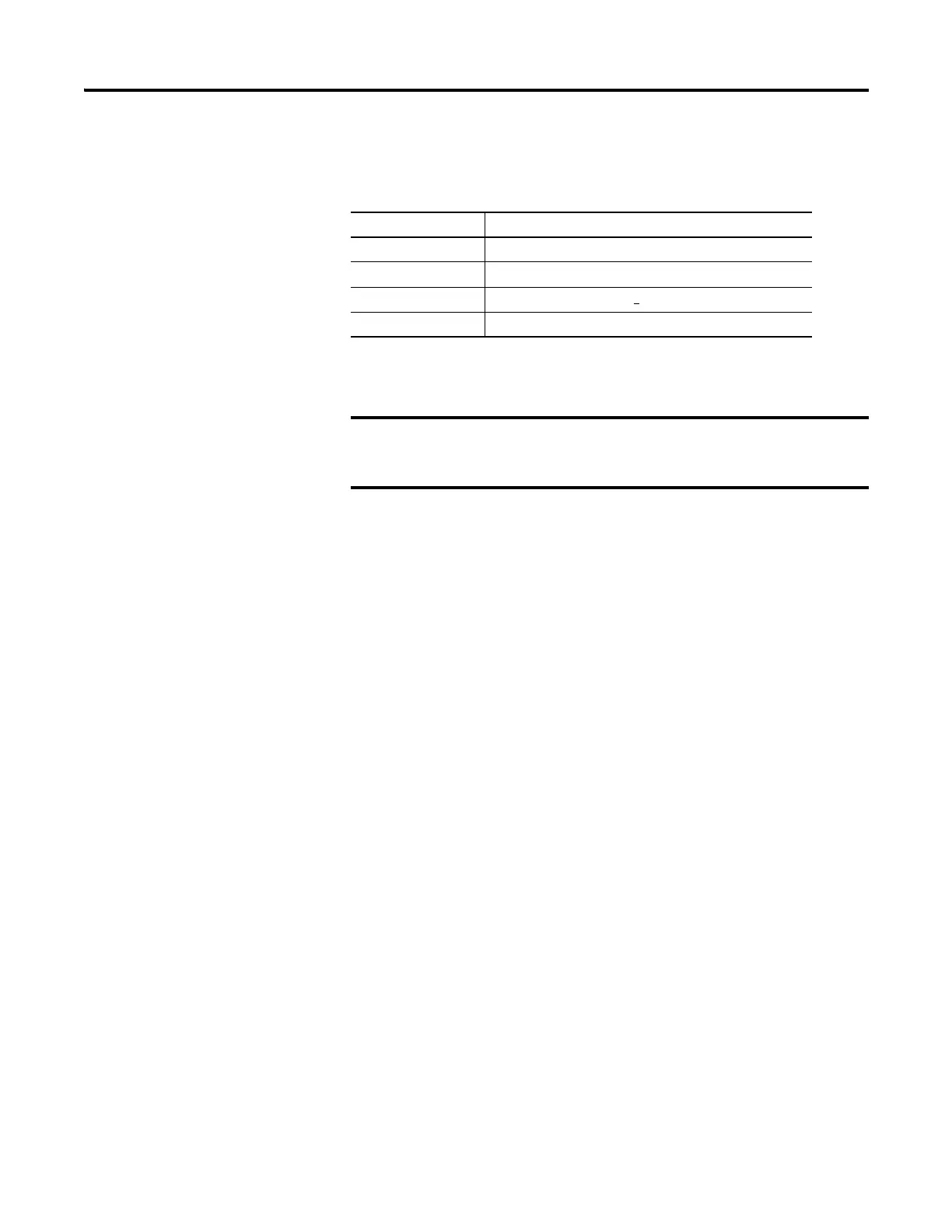
Module Recommended Instrument Range
1734-IE2C 1.00…20.00 mA (+/-0.15 μA) current source
1734-OE2C DMM better than 0.6 μA
1734-IE2V Voltage source 0.0…10.0V (+0.3 mV)
1734-OE2V DMM better than 0.5 mV
The module ignores output data sent to the module until
after calibration ends. This could be hazardous if active
control were attempted during calibration.
 Loading...


