Rockwell Automation Publication 1734-UM001E-EN-P - July 2013
Install POINT I/O Modules 11
The mounting base snaps into place.
4. To remove the mounting base from the DIN rail, remove any installed
module (and any module immediately to the right), and use a small-bladed
screwdriver to rotate the DIN-rail locking screw to a vertical position and
release the locking mechanism.
5. Lift straight up to remove the mounting base.
Install an I/O Module
Install the module before or after base installation. Make sure that the mounting
base is correctly keyed before installing the module into the mounting base. In
addition, make sure the mounting base locking screw is positioned horizontal
referenced to the base.
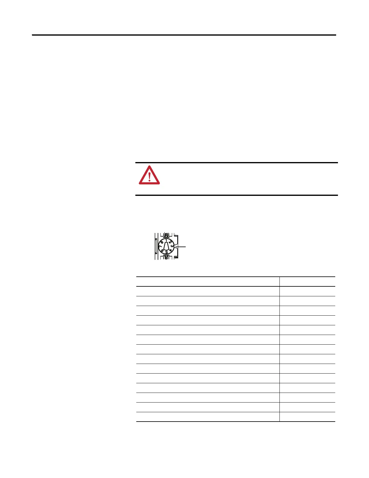
1. Using a bladed screwdriver, rotate the keyswitch on the mounting base
clockwise until the number required for the type of module aligns with the
notch in the base.
WARNING: When you insert or remove the module while
backplane power is on, an electrical arc can occur. This could cause
an explosion in hazardous location installations. Be sure that power
is removed or the area is nonhazardous before proceeding.
Module Keyswitch Position
1734-ARM
(1)
(1) Use the same keyswitch position as the removed module.
–
1734-CTM, 1734-VTM 5
1734-IA2, 1734-IA4 8
1734-IB2,1734-IB4, 1734-IB8 1
1734-IE2C, 1734-IE2V 3
1734-IM2, 1734-IM4 8
1734-IV2, 1734-IV4, 1734-IV8 1
1734-OA2, 1734-OA4 8
1734-OB2, 1734-OB4, 1734-OB8, 1734-OB2E, 1734-OB4E, 1734-OB8E 1
1734-OB2EP 1
1734-OE2C, 1734-OE2V 4
1734-OV2E, 1734-OV4E, 1734-OV8E 1
1734-OW2, 1734-OW4 7
1734-OX2 7
Notch Position 3 is shown
46148
 Loading...


